Lab 2 - IMU
Lab Tasks
Set up the IMU
To setup the IMU, the “SparkFun 9DOF IMU Breakout_ICM 20948_Arduino Library” was downloaded from the Arduino Library Manager. The IMU is connected to the Artemis board by using a QWIIC connector.
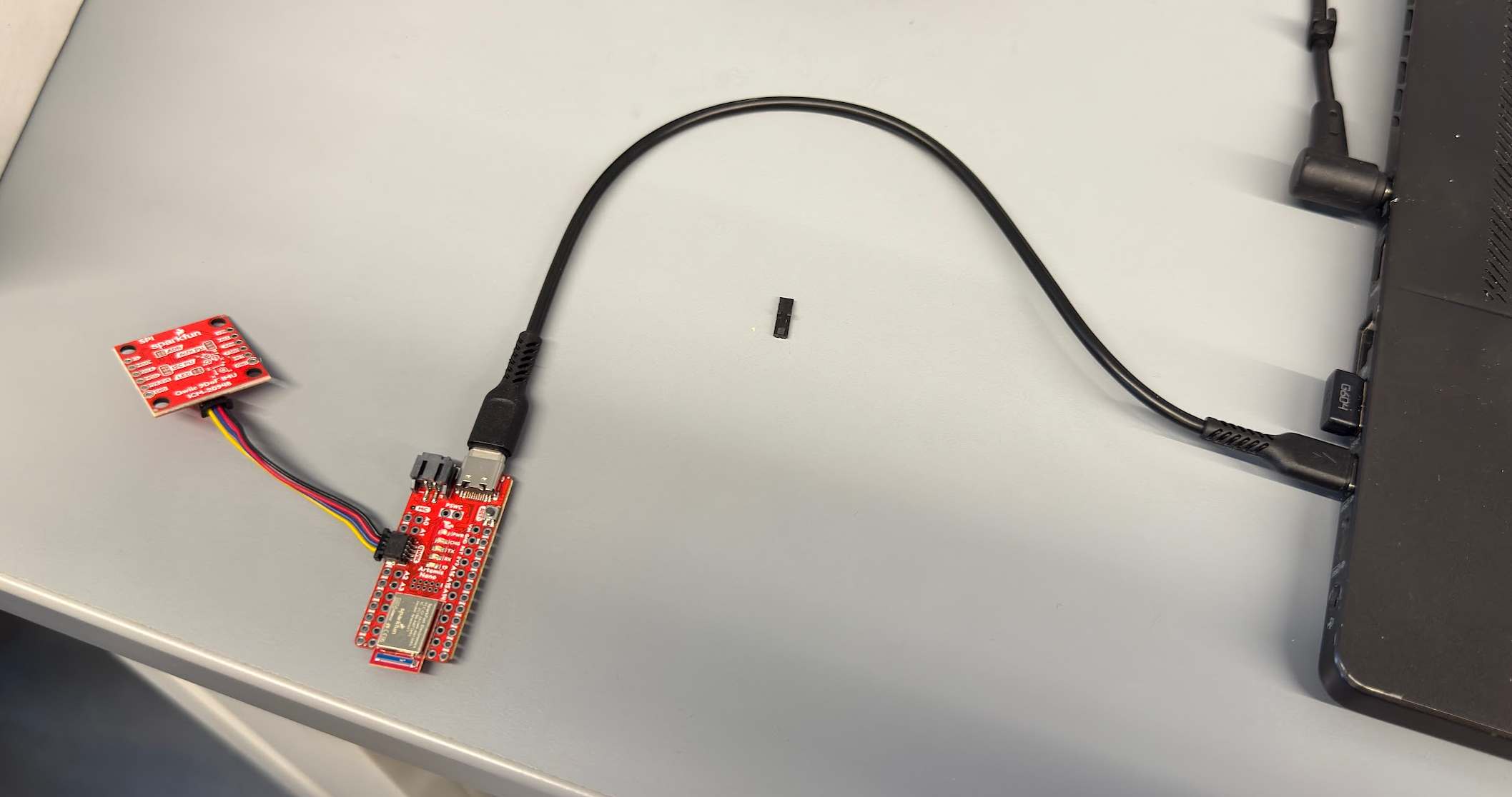
To ensure that the IMU is working, the IMU example code was ran. Within the code, the AD0_VAL represents the status of the IMU breakout. The default is 1, and when the ADR jumper is closed, the value becomes 0. To test the functionality of the IMU, I rotated the board in my hand. It is observed that the acceleration and gyroscope data rapidly change when the board is quickly rotated and updates frequently. The gyro data measures in degrees per second, and the acceleration data measures in mg.
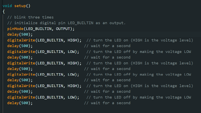
To indicate that the board is running, I added code to have the board blink three times on start-up. I wrote the following code in the Arduino sketch:
Accelerometer
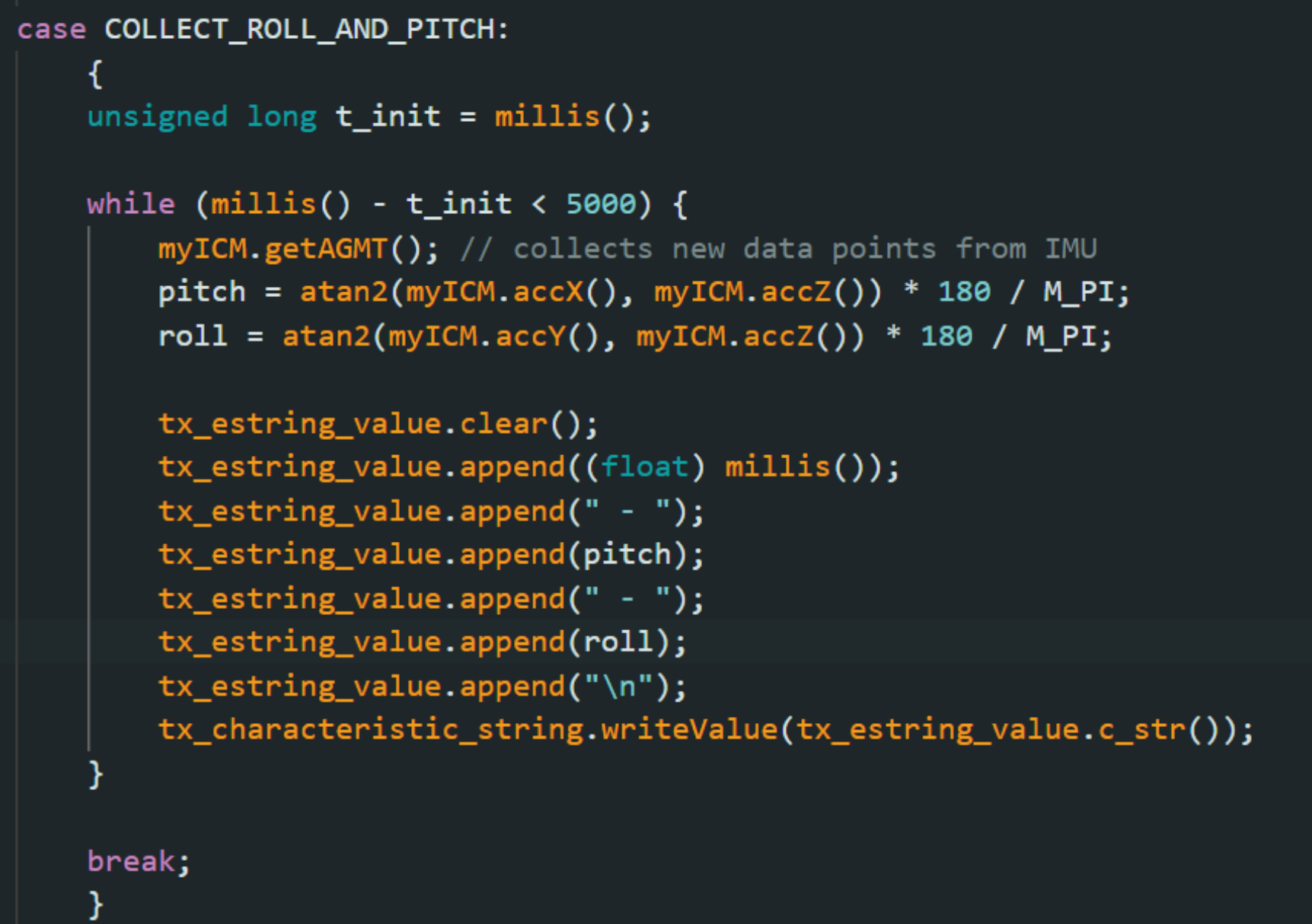
To convert the IMU data into pitch and roll measured in degrees, the following code was implemented:
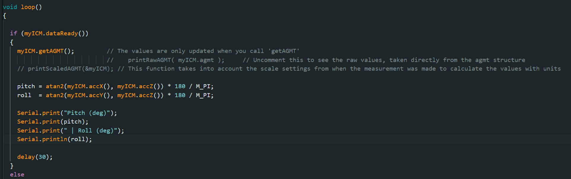
The following video shows the output when held at between -90 and 90- degrees.
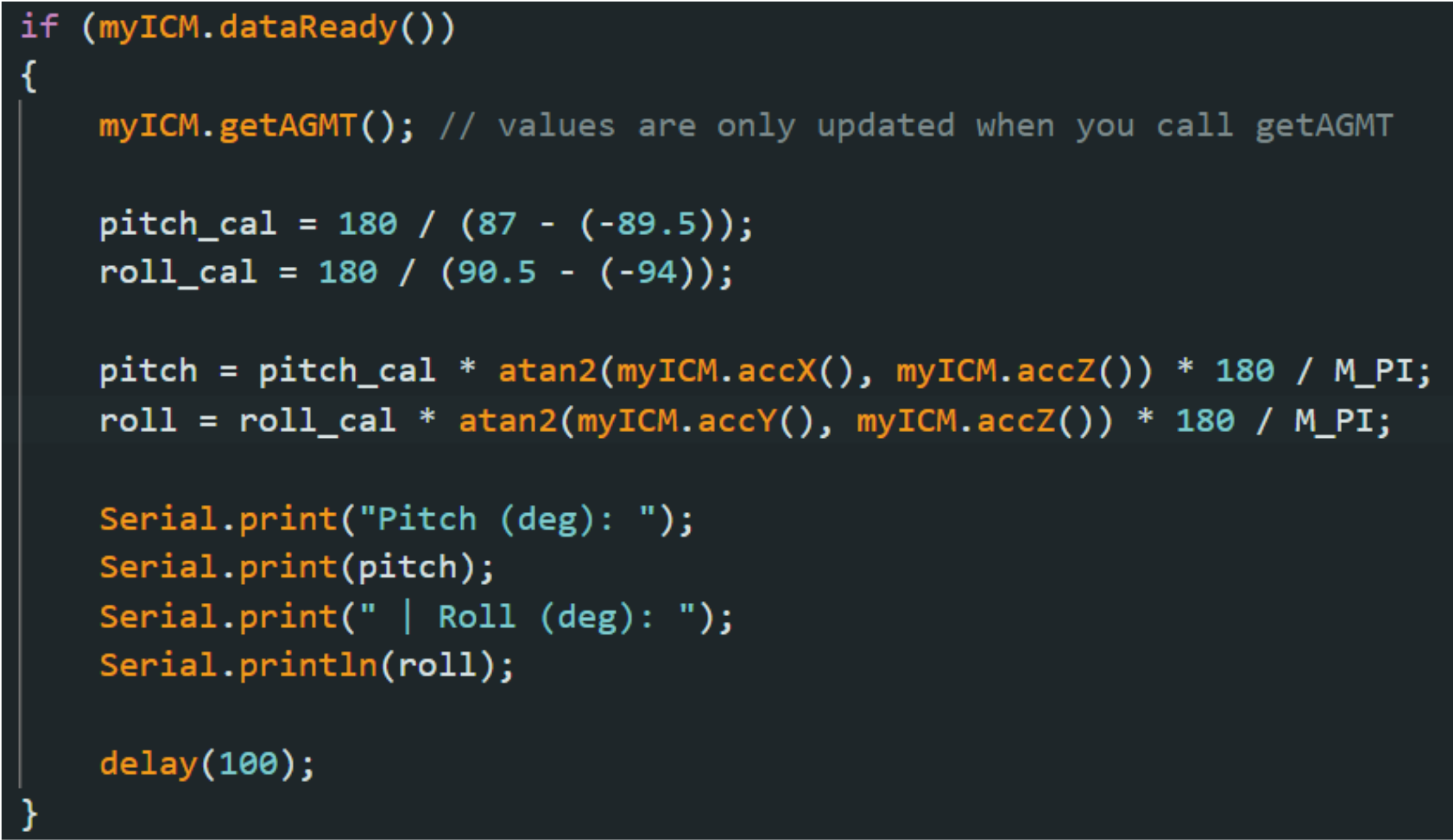
The accuracy of the accelerometer was not perfect and needs calibration. For pitch, when held at -90 degrees, the output is -89.5 degrees, and when held at 90 degrees, the output is 87 degrees. For roll, when held at -90 degrees, the output is -94 degrees, and when held at 90 degrees, the output is 90.5 degrees. The outputs are then used to create a 2-point calibration.
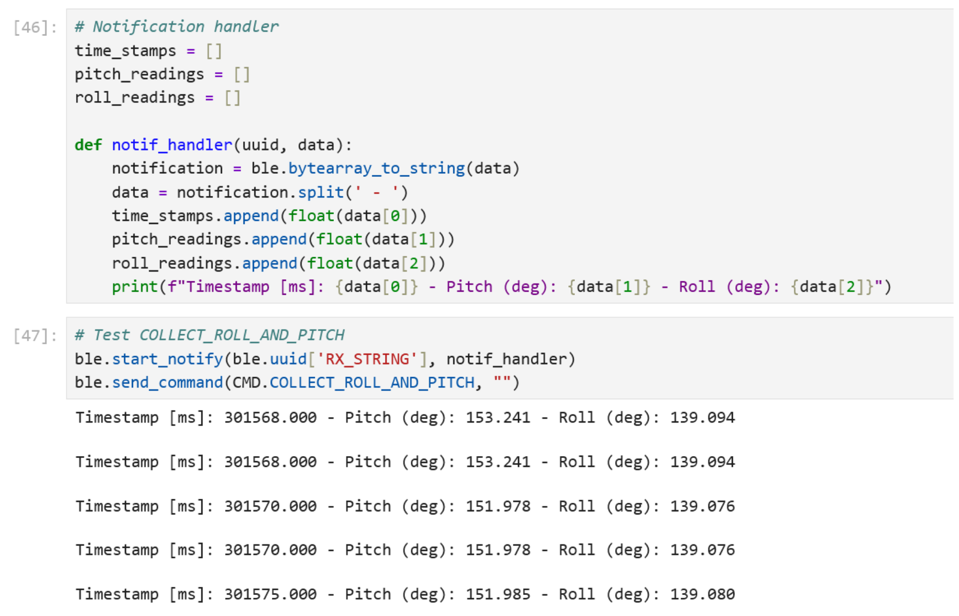
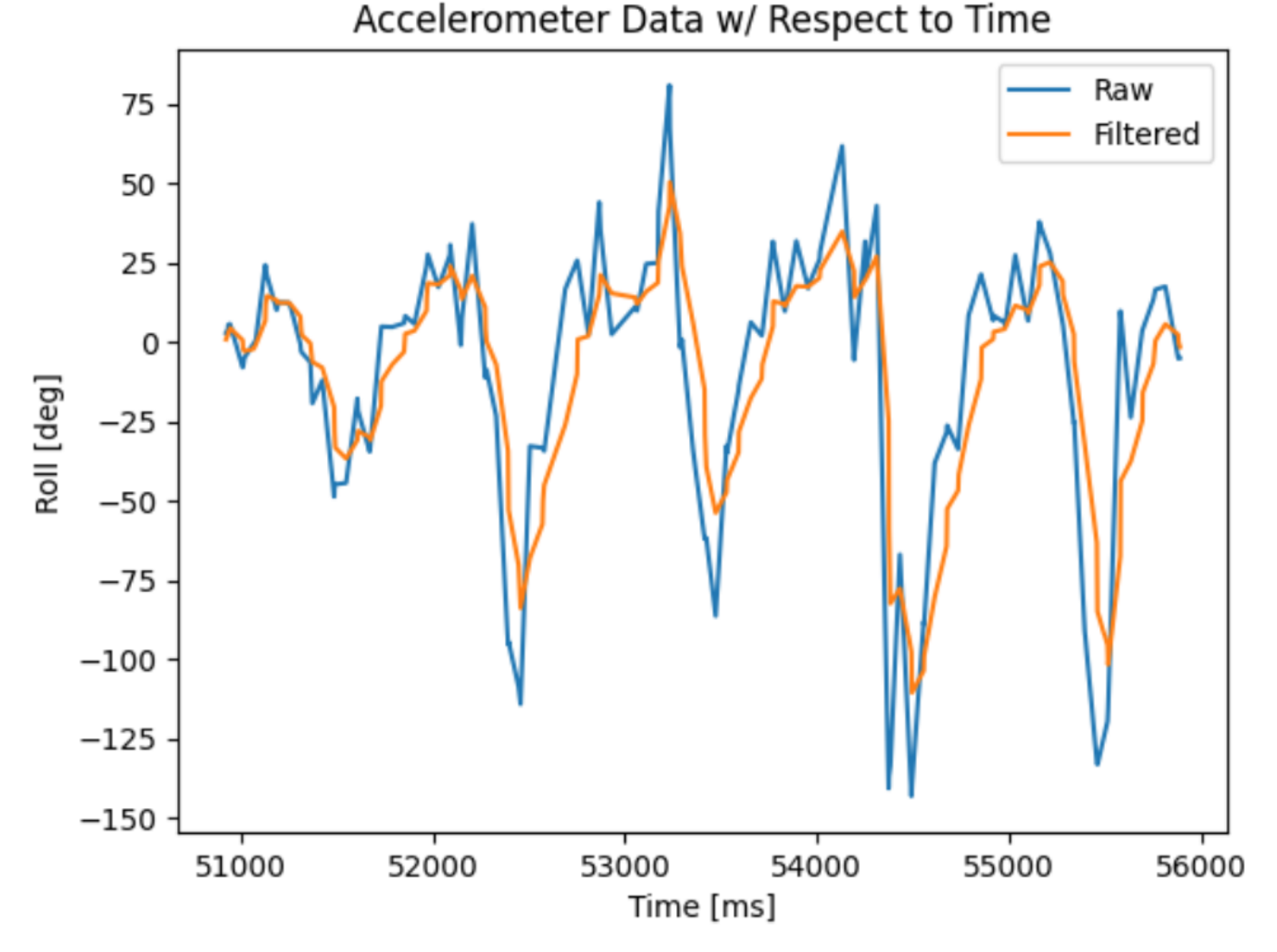
To post-process the data, the following command is written to collect roll and pitch data for a duration of 5 seconds. A notification handler was created in the Jupyter notebook to collect the data with associated timestamps.
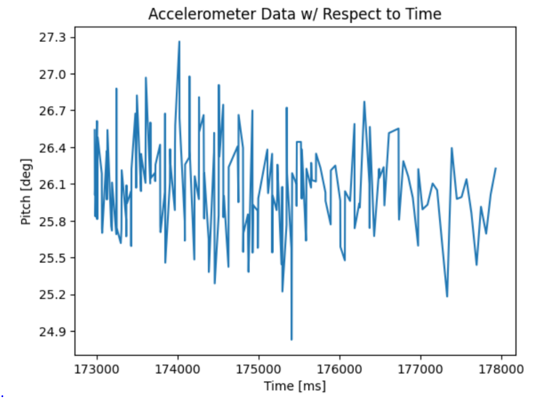
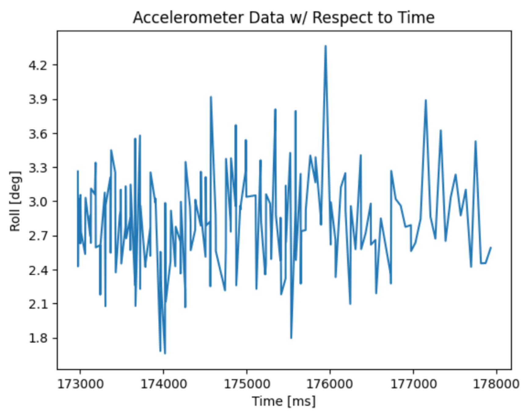
There is a decent amount of noise in the accelerometer sensors of the IMU. A FFT was used to analyze the noise.
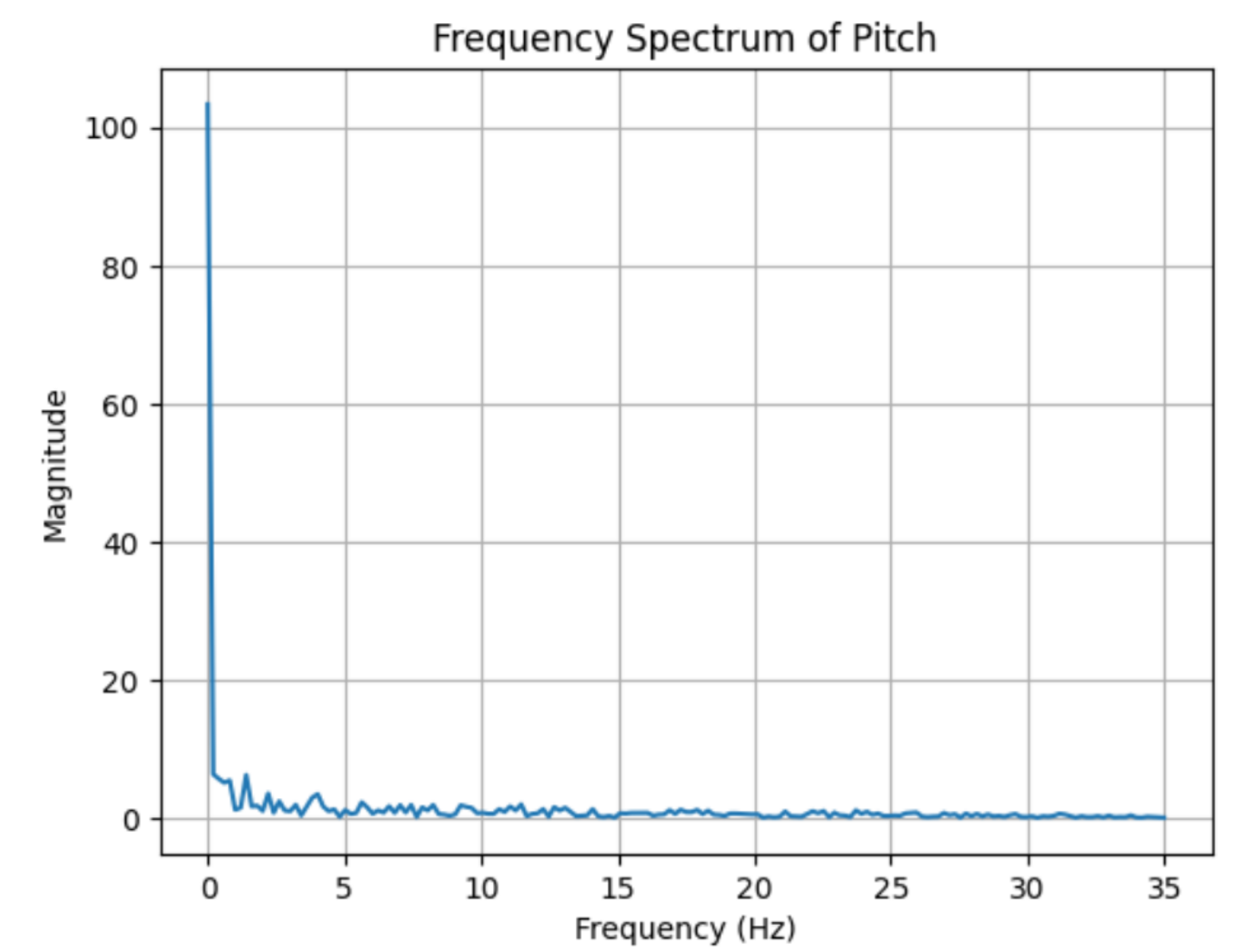
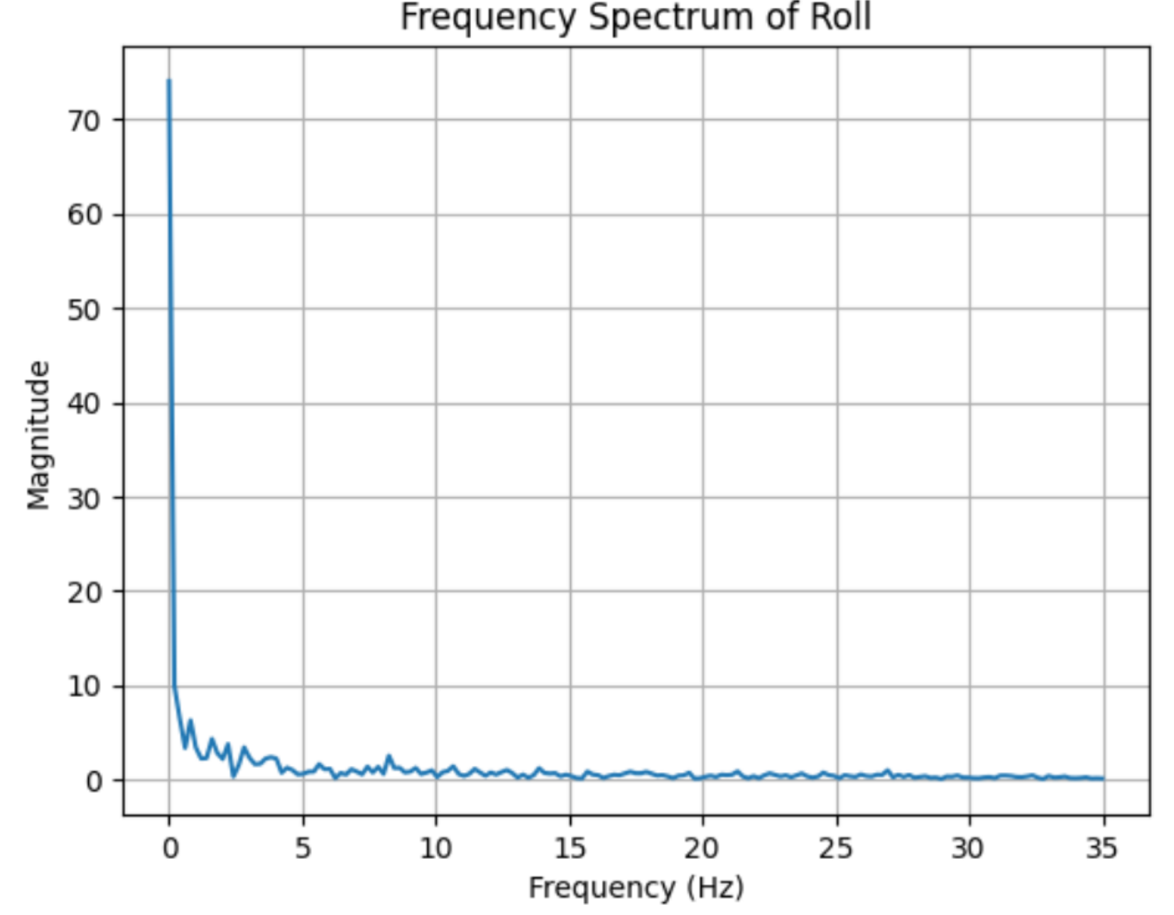
From the above figures, I decided to choose a cutoff frequency of 5 Hz, as much of the data points were collected within this range. The cutoff frequency greatly affects the amount of frequencies that is allowed to pass through and the amount of noise removed. It is important to choose a cutoff frequency that is low enough to remove high frequencies while maintaining sensor data.
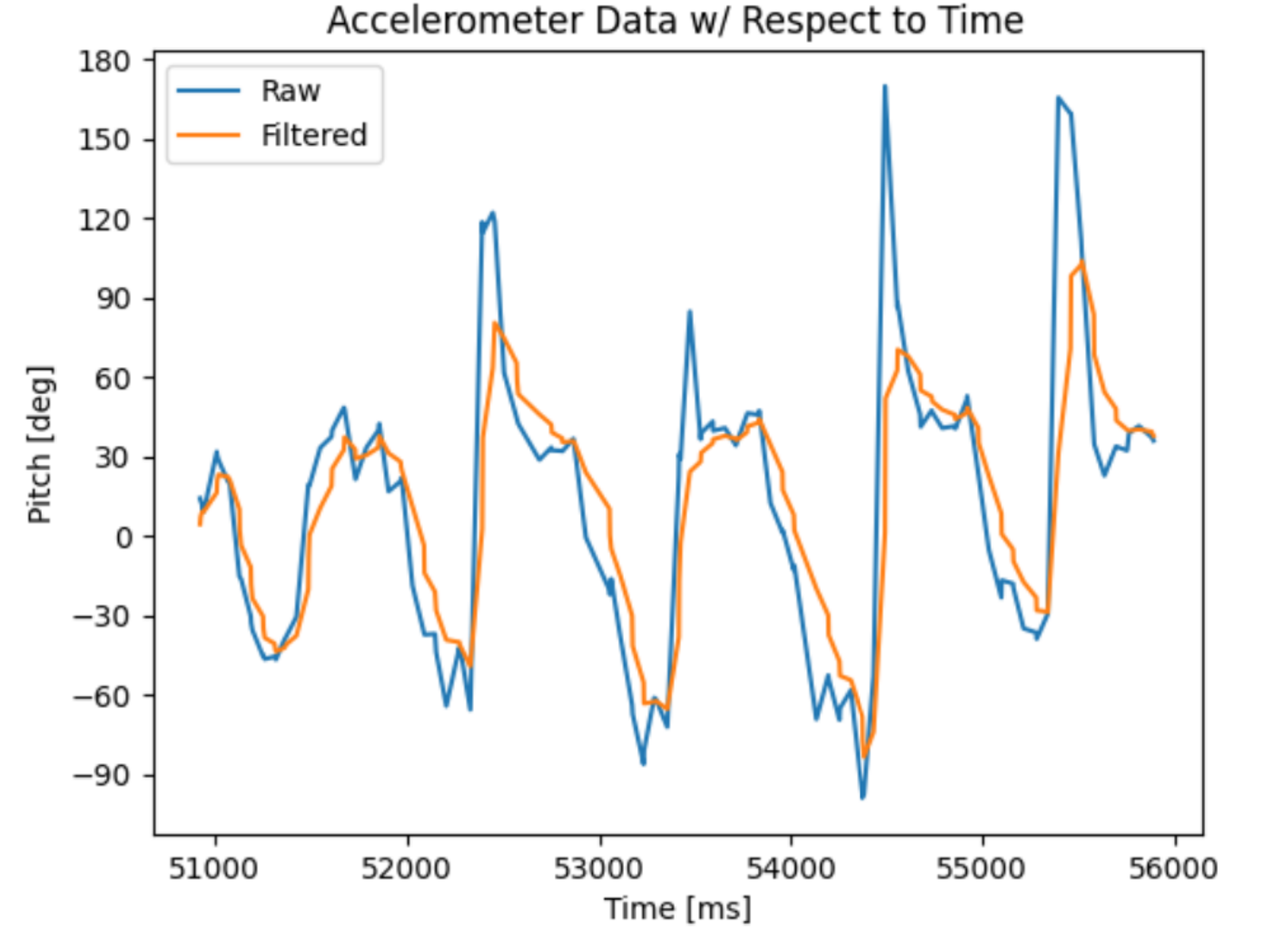
A low pass filter is implemented into the code. By using the equation:
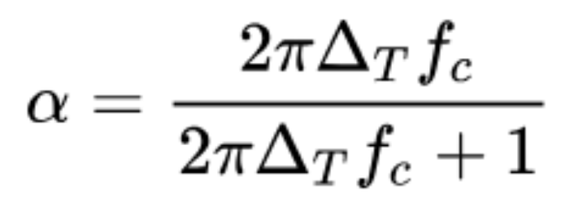
With a cutoff frequency of 5 Hz, and a sampling spacing of 0.01421 seconds, the alpha is 0.3087.
Gyroscope
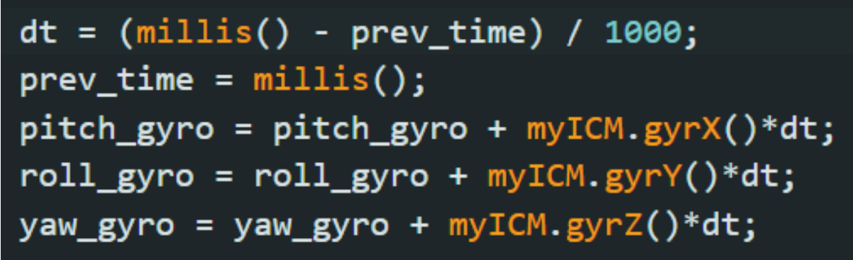
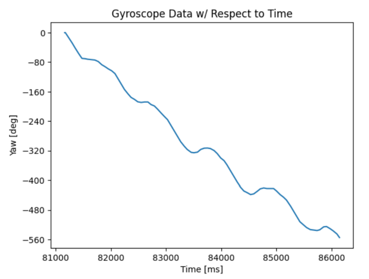
To calculate pitch, roll, and yaw angles from the gyro, the following code is written:
After rotating the IMU for a duration of 5 seconds, the following data was collected:
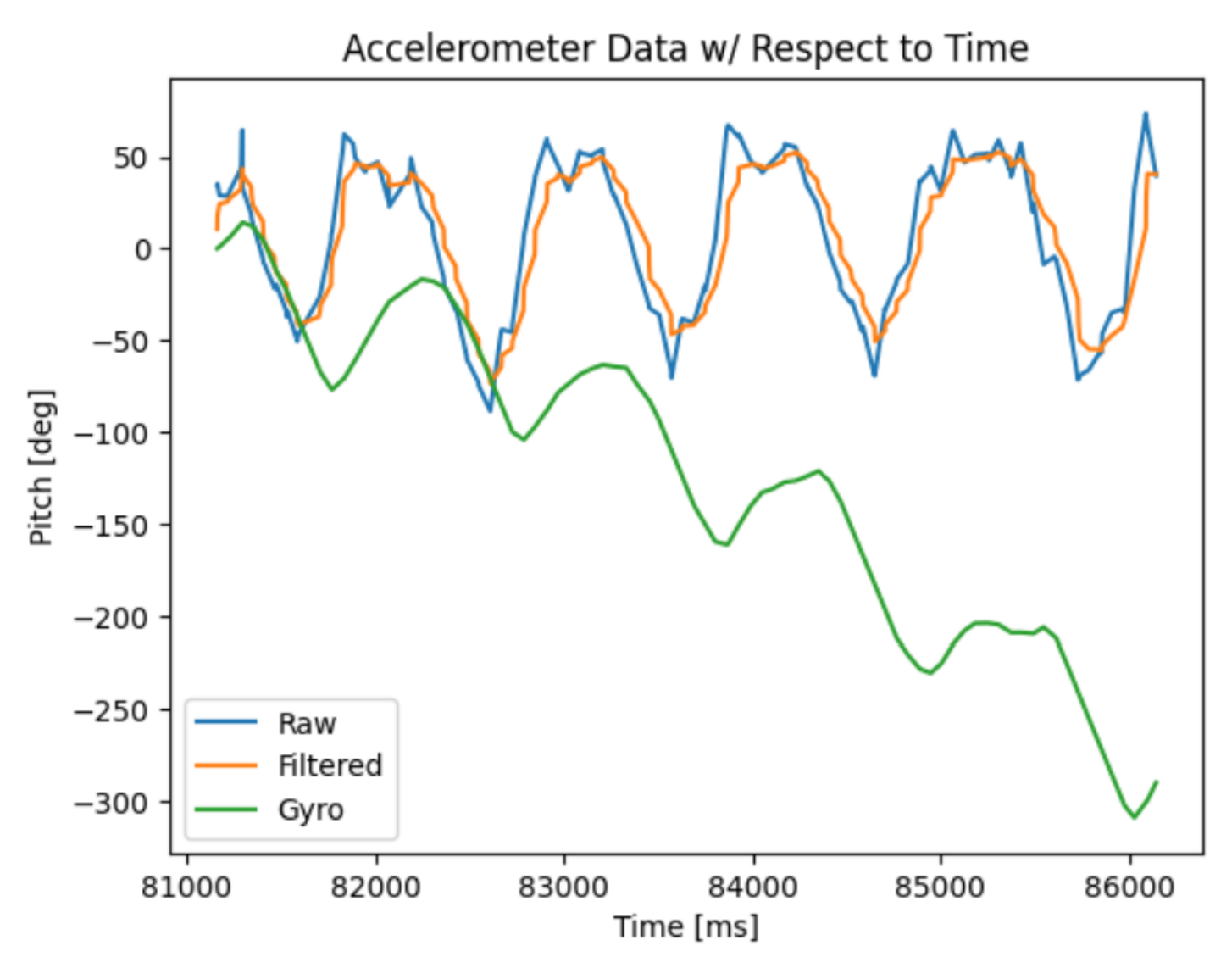
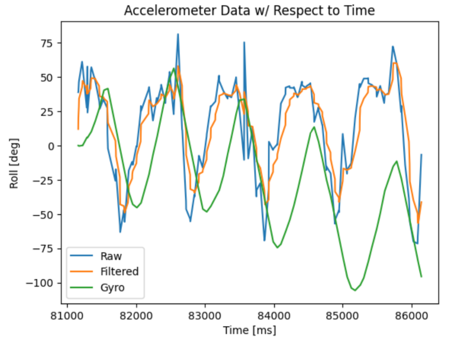
Compared to the accelerometer, outputs from the gyro have significantly less noise but will drift within a short period of time. To make the data more accurate and stable, a complementary filter was implemented:

With an alpha value of 0.9, the filter created data that is stable against oscilations and vibrations (which I created by tapping the table).
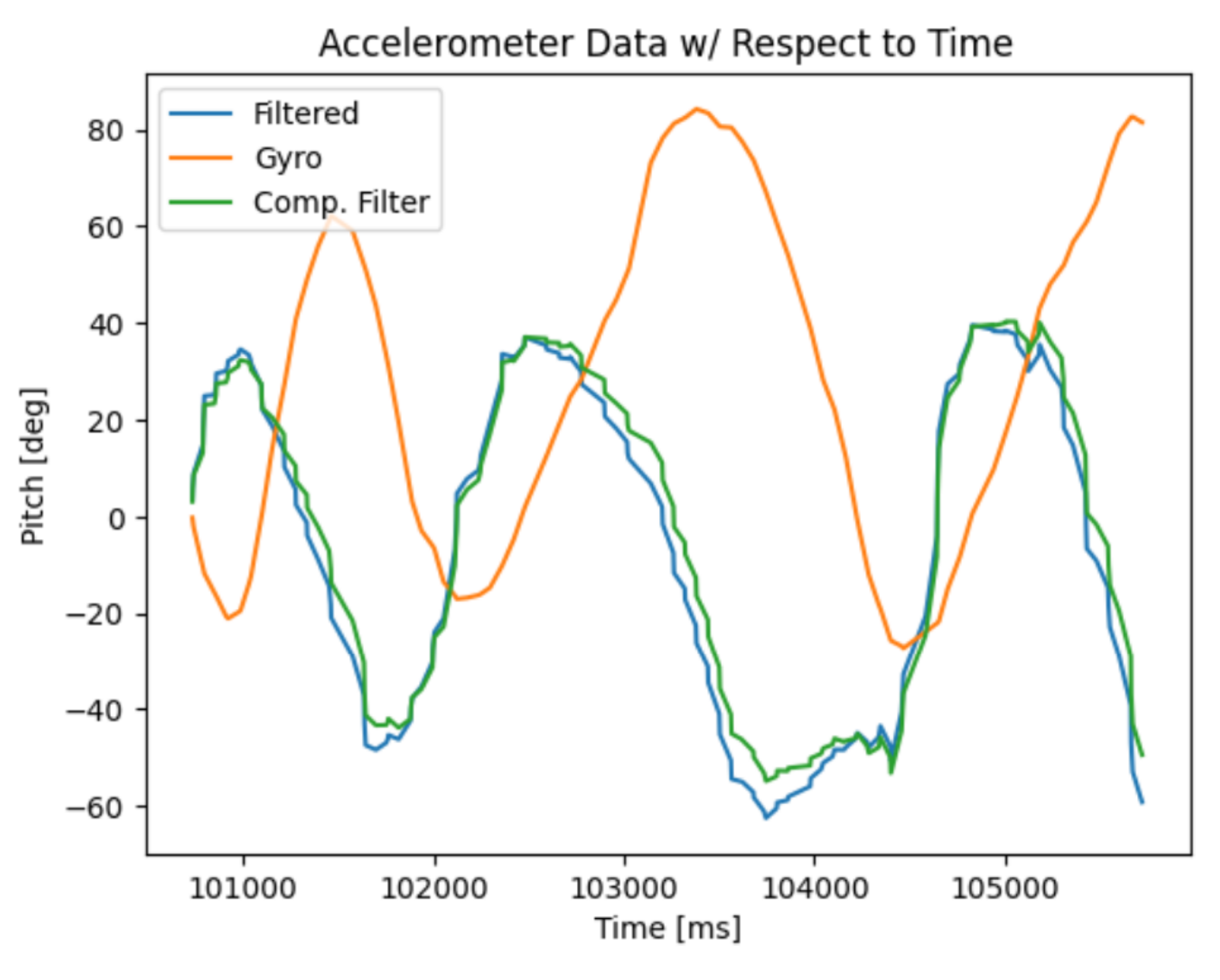
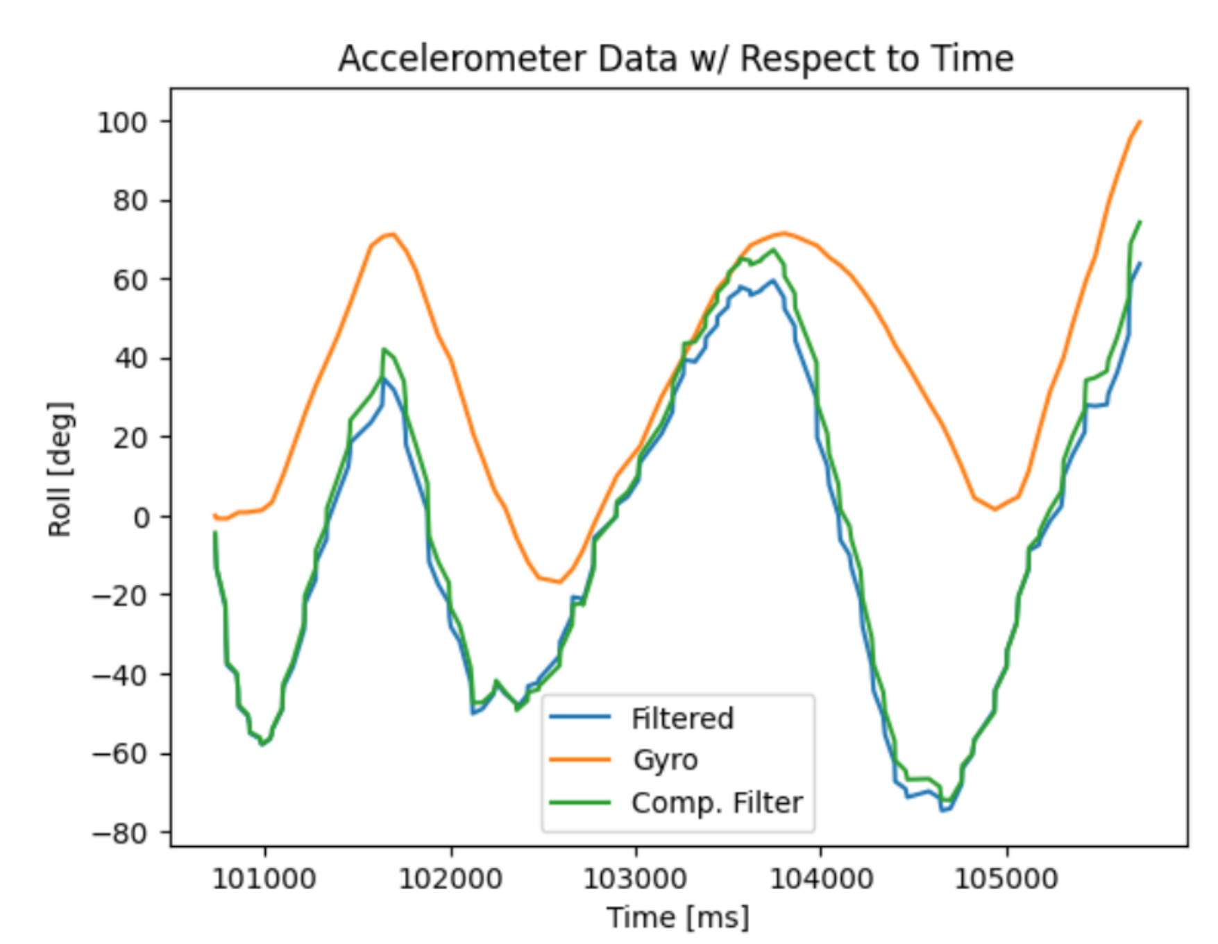
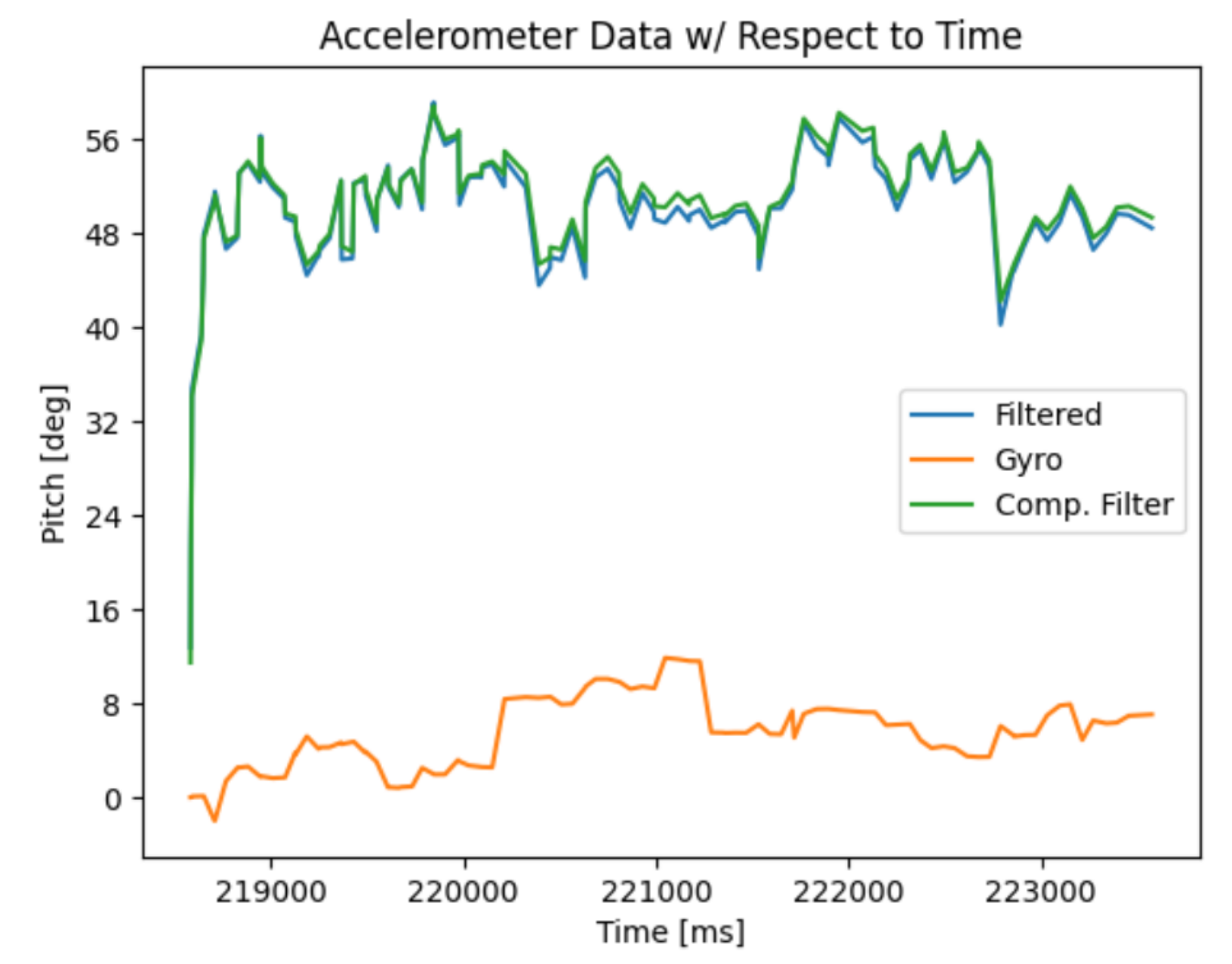
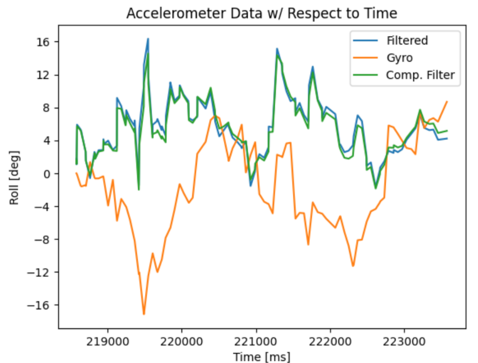
With a high alpha value, the filter relies more on the accelerometer data than the gyro data. I chose this value to minimize the amount of drift induced by oscillations of the sensor and from vibrations.
Sample Data
Within my code, I do not use the command if (myICM.dataReady()) and instead explictly call for myICM.getAGMT(). By using this method, it does not need to wait if the data is ready and allows me to directly collect data from the IMU once it is updated. Currently, there are no delays inserted the code for debugging nor any Serial.print statements.
For the storage of data, it is more sensible to store separate arrays for accelerometer and gryoscope data. This allows for simpler code in which each set of data is in its respective array that is also smaller in size. It also allows for the collection of data for one sensor at a time while not needing to collect data from both sensors. The best data type to store your data is the one that takes the least amount of space. From the given data types, unsigned longs should not be used as they cannot store negative values. Strings and doubles also take more space, so floats are the best data type to be space-efficient.
Record a Stunt
The RC vehicle is capable of accelerating quickly back and forth. When traversing in one direction, a reverse input would cause the vehicle to flip over. With enough practice, you are able to make the RC dance in a tight spot. While not shown in the video, the RC is also capable of turning very quickly.
Discussion
This lab teaches how to collect and process IMU data, such as calibration, fusing sensors to obtain more accurate data, and how to increase execution of code when handling large amounts of data.
Collaborators
For Lab 2, I collaborated with Sean Zhen (sz378). I also used pages from last year as references from Selena Yao and Angela Voo.
Back to Labs