Lab 3 - Time of Flight Sensors
1. Prelab
The I2C sensor address for the ToF sensors is 0x52.
Because the sensor address is hardwired on the board, there are two ways to operate the two ToF sensors:
- Change the address programmatically
- Continuously enable/disable each sensor through the shutdown pins
Out of the two approaches, I will use the first approach. Having two sensors enabled at the same time allows the robot to have a wider range of distance data, giving more confidence on where the car is at any time. There is also less logic required as the car does not need to decide when to enable or disable a ToF sensor. This will make the integration of the sensors easier to code.
Because the I2C addresses reset to default after a power cycle, the address needs to be changed programmatically each time it is turned on. To do this, each sensor needs to be brought out of reset individually and have a unique address assigned. This can be done by connecting a wire from one of the sensor’s XSHUT pin to a digital output on the Artemis Nano and disabling the sensor on power-up, assigning the address to the sensor, and re-enabling it.
One of the sensors will be placed on the front of the car. Because the car spends most of the time driving forward, a sensor placed on the front will prevent it from driving into any obstacles. The ToF sensors have a FoV of 27 degrees, so the second sensor should be placed on the right side of the vehicle. This will give the car a wider range of detection of any obstacles while driving forward. The placement of these sensors do create a blind spot for the car on its left and rearward sides. This means that if the car needs to turn left or reverse, it will not detect a obstacle and will potentially collide into it.
The following diagram shows the approximate placment of the ToF sensors and other components within the chassis of the car.
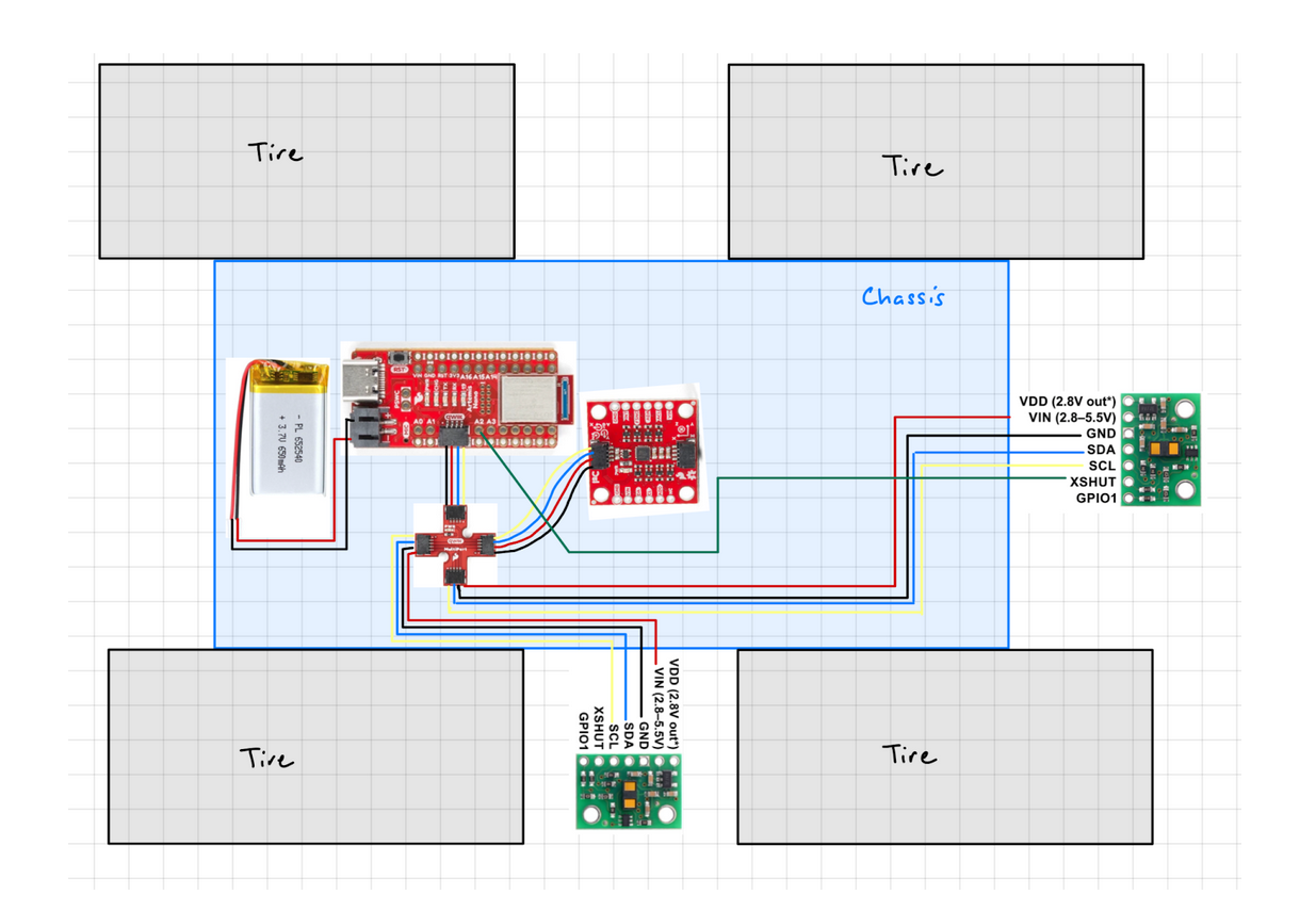
Both ToF sensors will have the longer QWIIC cable soldered to its conneciton points, and the IMU will use the shoter QWIIC cable. This will allow flexbility of the placment of the two ToF sensors.
2. Lab Tasks
1. Powering up the Artemis with a Battery
To power up the Artemis, a JST connector was soldered to a 650 mAh battery. On the JST connector, the black-colored wire is positive, and the red-colored wire is negative. This means that the opposite colored wires need to be soldered to the battery’s wires.
After powering up the Artemis, the board was not connected to the laptop’s USB-C port to ensure that messages can be sent back and forth through Bluetooth.
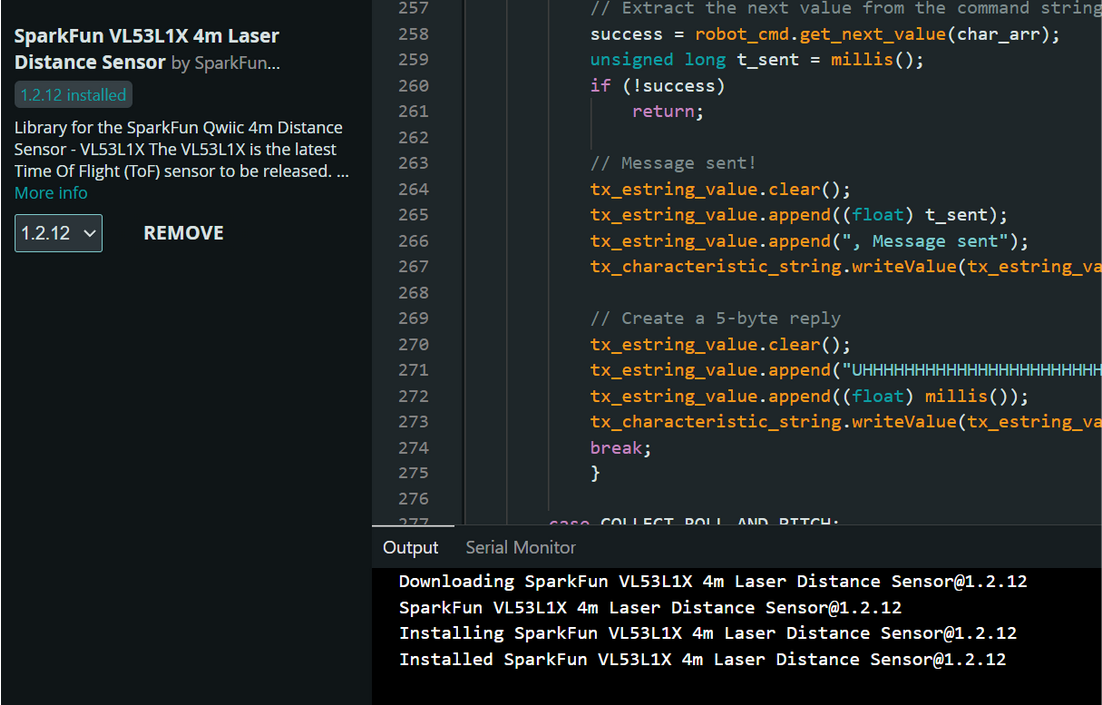
2. Install the SparkFun VL53L1X 4m laser distance sensor library
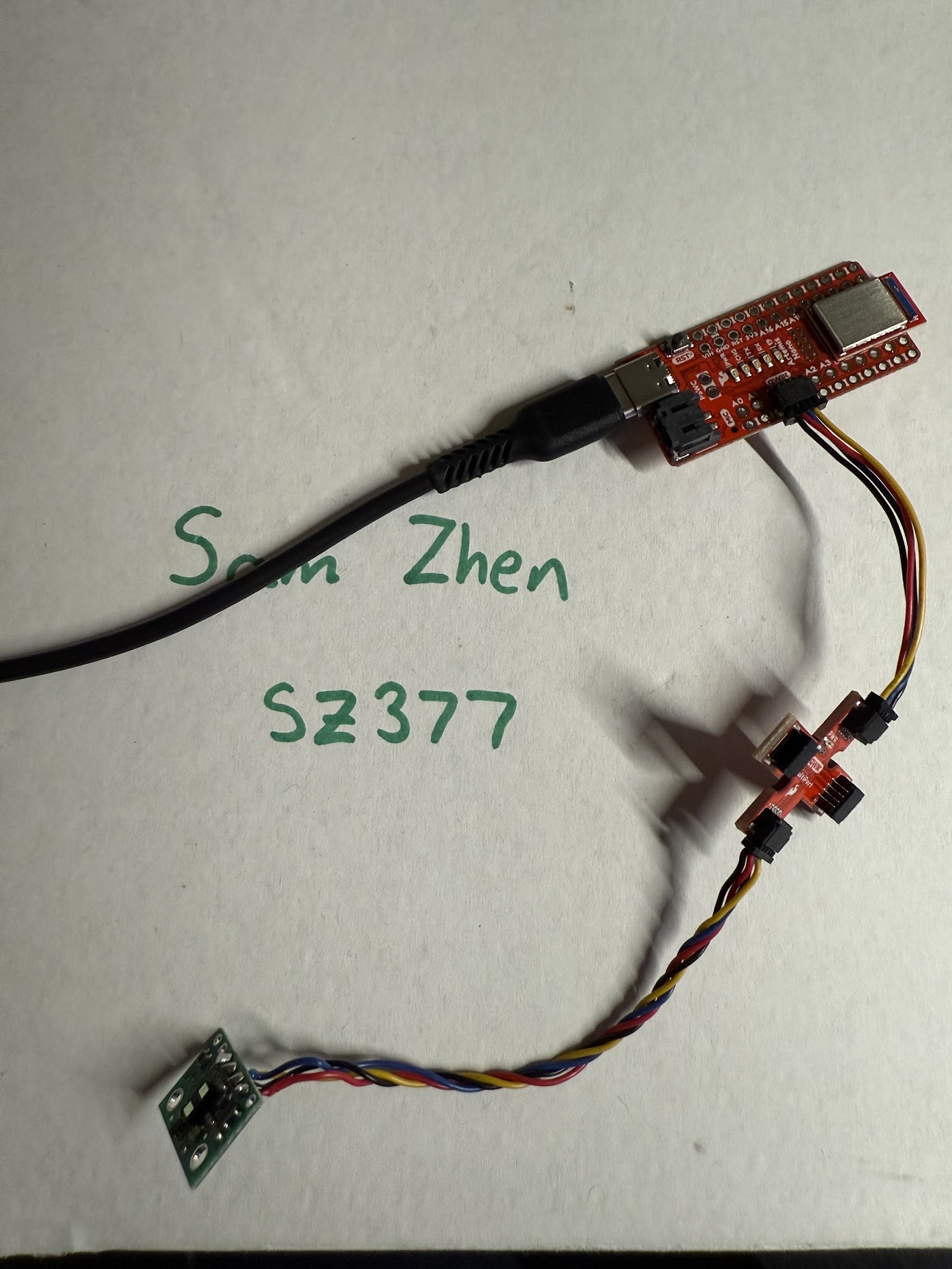
3. Connect the QWIIC break-out board to the Artemis
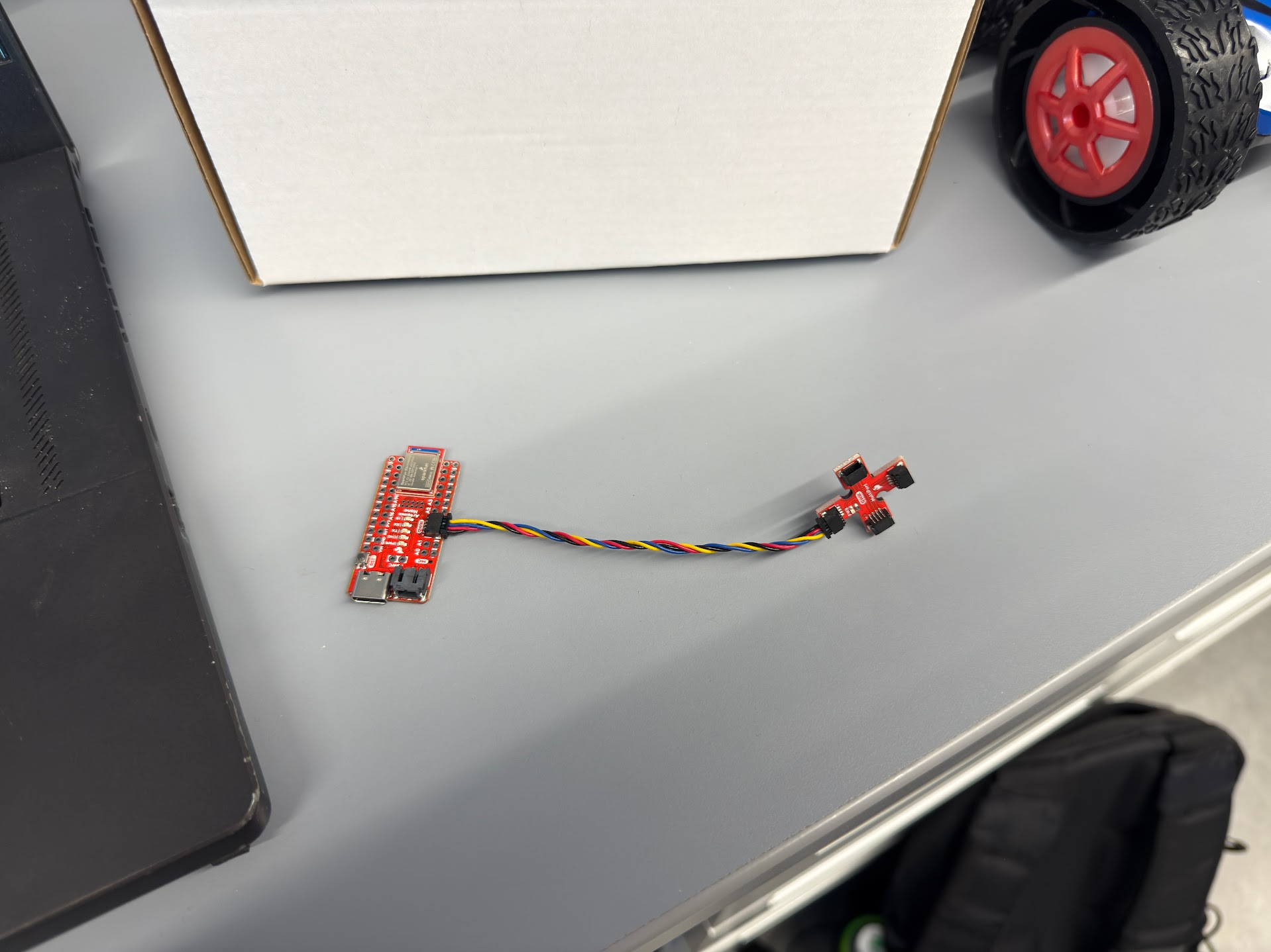
4. Connect the first ToF sensor to the QWIIC breakout board.
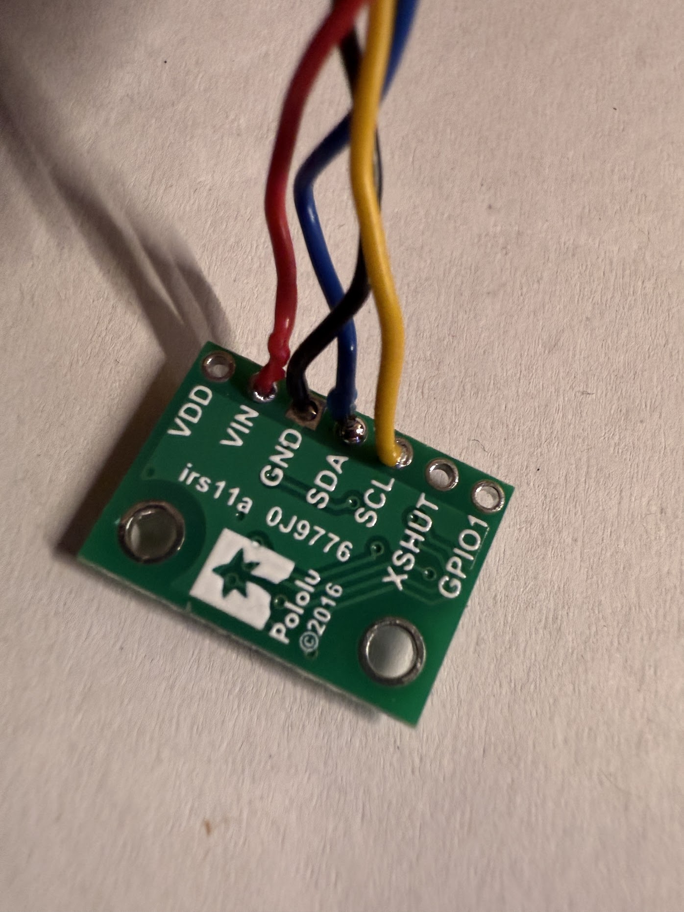
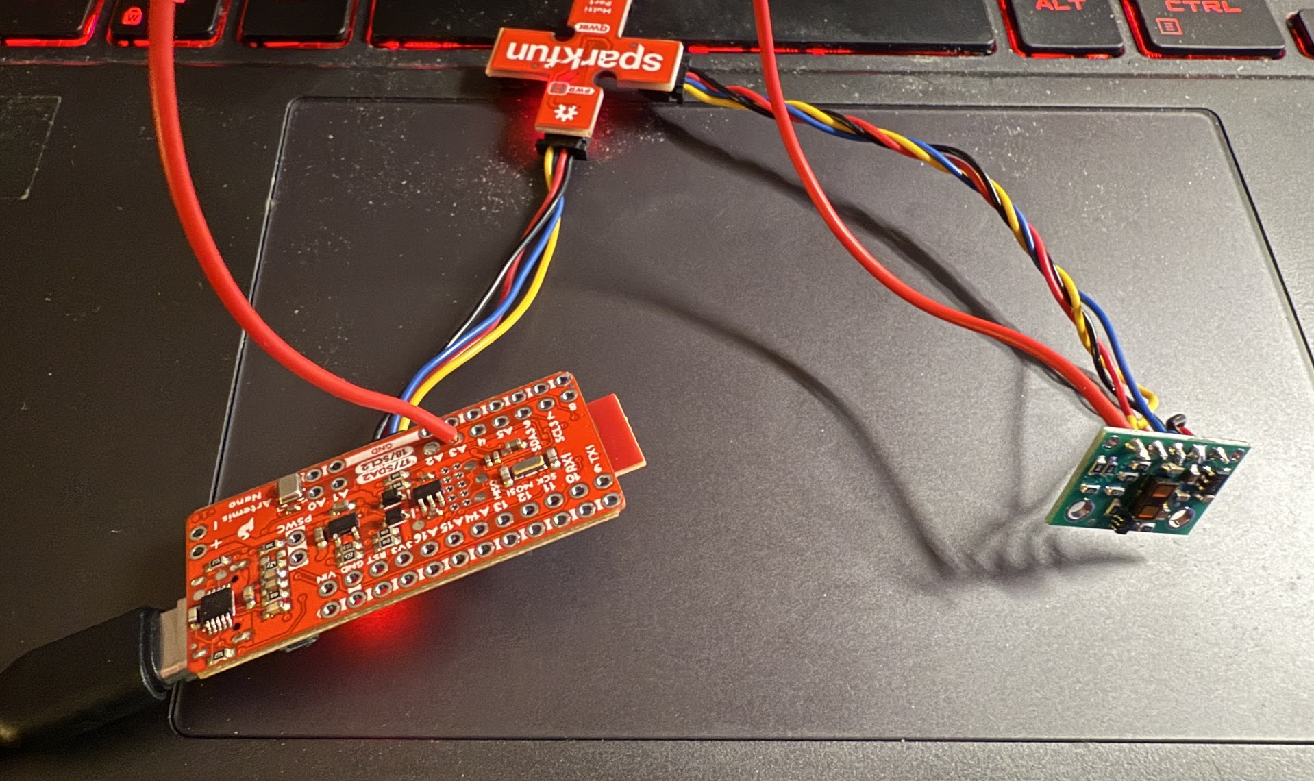
To connect the ToF sensor to the QQIIC breakout board, a QWIIC cable needs to be soldered to the sensor. With two long cables and two short cables in the kit, I decided to solder the longer cables to allow flexibility during mounting of the sensors in the future.
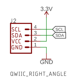
Following the documentation provided for the breakout board, the red wire connects to VIN, the black wire connects to GND, the bleu wire connects to SDA, and the yellow wire connects to SCL.
5. Scan the I2C channel to find the sensor
To find the sensor on the I2C channel, the Apollo3 Example05_wire_I2C sketch was ran. With one of the ToF sensors connected to the breakout board, the following messages are shown on the Serial Monitor:
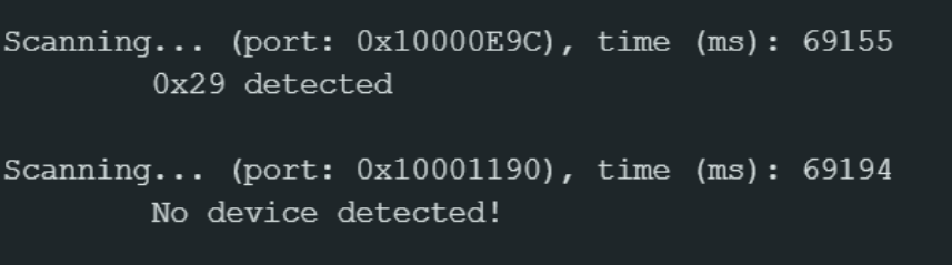
While the 0x29 address does not match the expected 0x52 address, 0x29 represents the shifted 7-bit address, while 0x52 represents the 8-bit address. Arduino uses the 7-bit format, so the 0x29 address is expected.
6. Pros/cons of each operating mode
The ToF sensor has a Short, Medium, and Long mode.
Long distance mode allows the maximum detection distance of 4 meters, but its accuracy is affected by ambient light. It has a maximum sampling rate of 30 Hz.
Medium mode can detect objects up to 3 meters, with some resilience to interference from ambient light. It also has a maximum sampling rate of 30 Hz.
Short mode can detect objects up to 1.3 meters, and has the highest sampling rate of 50 Hz. It is also the most resilient to interference from ambient light.
To have the most frequent amount of distance data sent to the Artemis, short mode would be the best for the final robot. With a detection range of about 4.3 feet, short mode is sufficient enough for the robot to detect obstacles and avoid it.
7. Test your chosen mode
For the given reason above, I will be testing the ToF sensor in short mode and measuring its range, accuracy, repeatability, and ranging time.
To record distance measurements, a command was created to measure distances with the ToF sensor a period of 5 seconds.
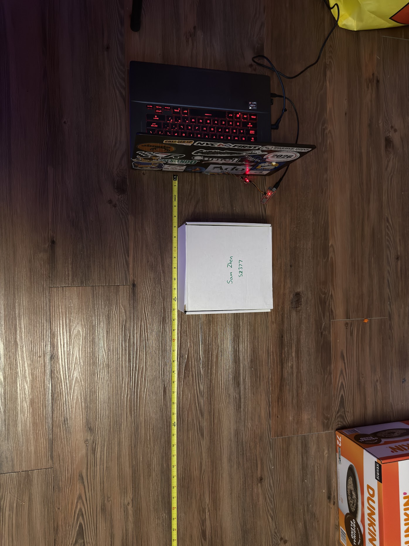
Using the back face of my laptop, the ToF sensor was taped approximately 1 to 2 inches from the ground. The white cardboard box that contains the robot kit is used as the object to detect by the sensor. The box is placed starting at 5 inches from the sensor and 5 seconds of data is collected. After the data is collected, the box is shifted farther away by an interval of 5 inches, and the data is collected again. This is repeated until the box is 60 inches away from the sensor.
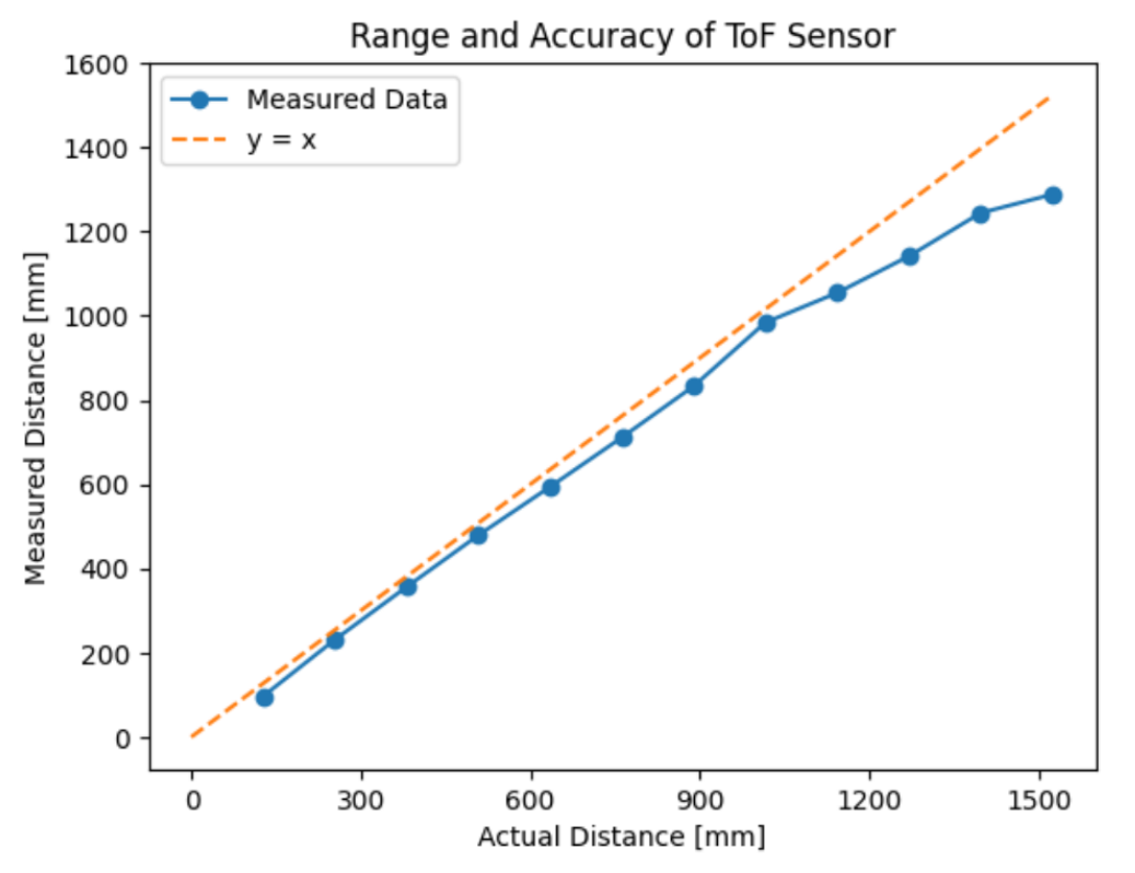
From the above figure, the maximum range of the sensor in short mode is ~1288 mm, which is close to the advertised range for short mode. The accuracy of the sensor can be up to 57 mm off from actual for distances between 0 mm to 900 mm. Anything farther than 900 mm away from the sensor will have larger and increasing errors up to 129 mm at the maximum range of the sensor.
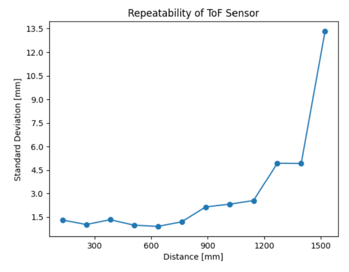
The standard deviation of the measured distances is low for distances between 0 mm to 1200 mm. Anything farther than 1200 mm will have significant variances in measured distances.
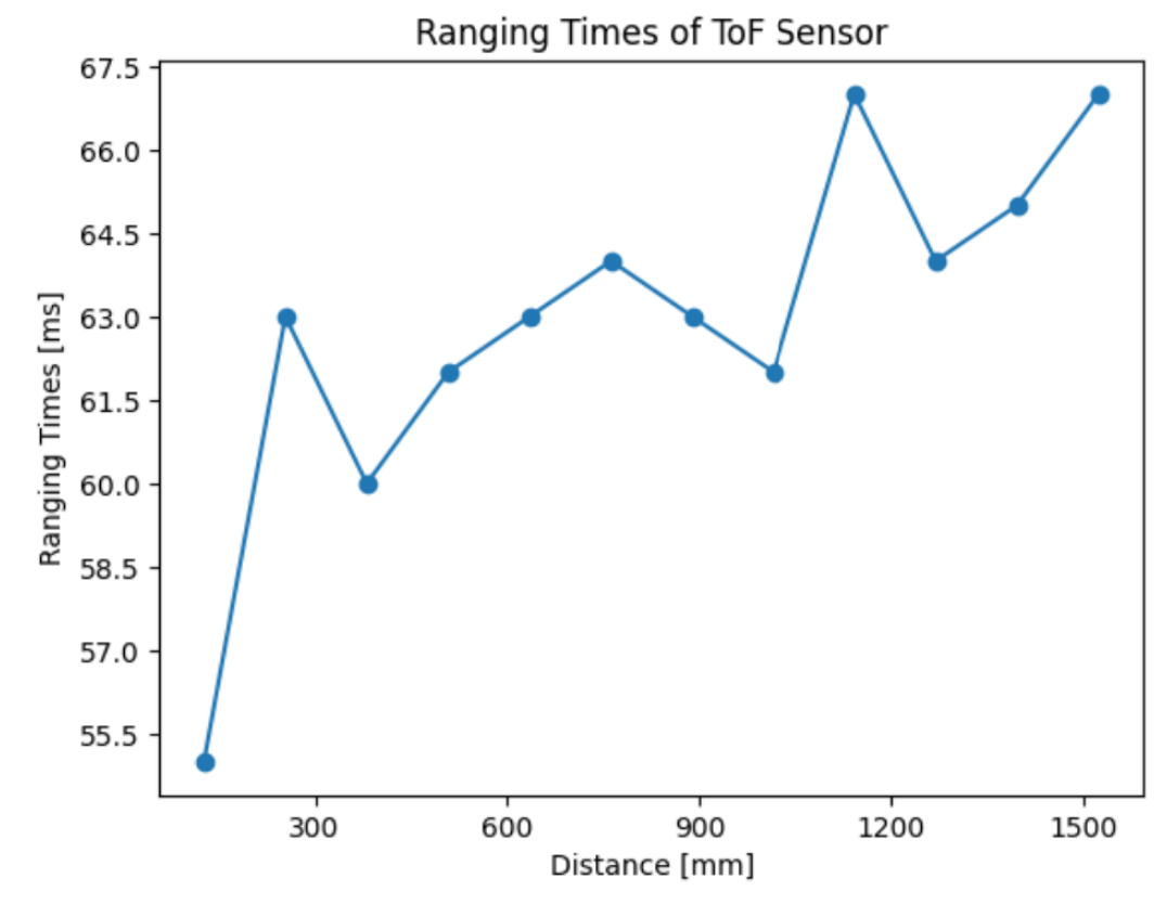
The ranging time of the sensor is fairly consistent across the range of the sensor. Ranging times start at ~55.5 ms at 127 mm and slowly incerase up to 67 mm at max range.
8. Hook up both ToF sensors simultaneously
To have two ToF sensors collect distance measurements at the same time, each sensor needs to have a unique address. To do this, a wire needs to be soldered to the XSHUT pin of the ToF sensor to one of the digital outputs on the Artemis Nano.
A wire was soldered from the XSHUT pin to the A3 pin on the Artemis Nano.
Within the Arduino sketch, the following code was written:
To demonstrate that both ToF sensors work, the previous READ_DISTANCE_5_SEC command was edited to output two distance measurements at the same time. A notifiation handler was created to show the outputs from the two sensors.
9. Print the Artemis clock to the Serial as fast as possible
To print the Artemis clock as fast as possible, the checkForDataReady() function is utilized to check whether new data is available from each sensor. If it’s not, the loops does not wait for new data to be available and moves on through the loop. The following implementation is shown below:
On the serial monitor, the following ouputs look like this:
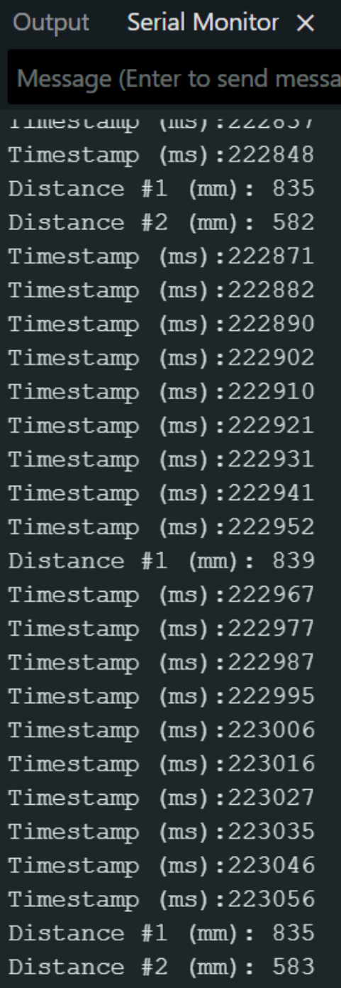
The loop executes every 8 to 11 ms, which is faster than how frequent the ToF sensors have new data ready, which is currently about 104 ms. Because the sensors update slower than the loop time, the sensors are the limiting factor.
10. Record time-stamped ToF data and IMU data for a set period of time
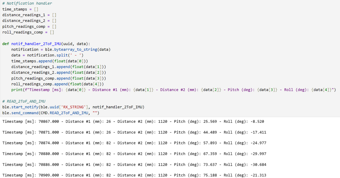
A new command was written to collect IMU data and ToF data at the same time-stamp for a duration of 5 seconds. The implementation is shown below:
The data is sent over to a notification handler, and the following data is received:
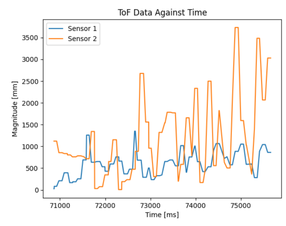
11. Include a plot of the ToF data against time
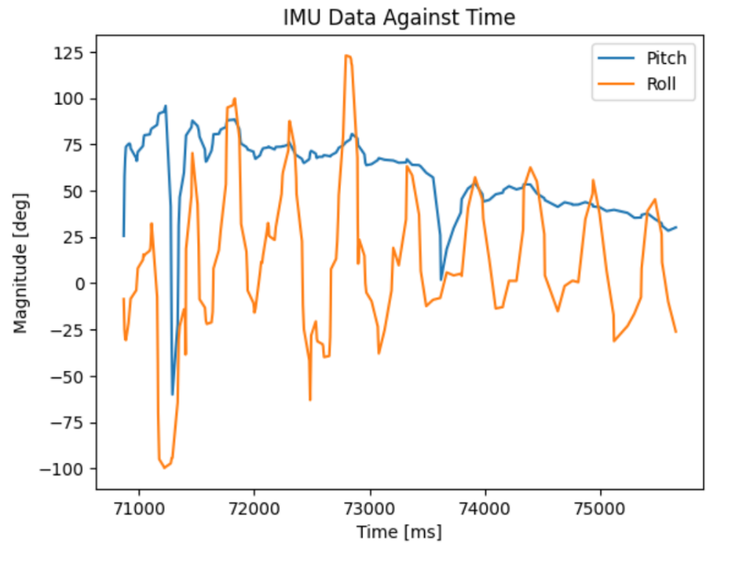
12. Include a plot of the IMU data against time
Additional tasks for 5000-level students
Discussion on infrared transmission based sensors
One type of sensor that is based on infrared transmission is a IR triangulation sensor. It determines the distance of an object by measuring the angle of the reflected beam and calculating the distance based on the angle. These type of sensors are best for short-range distances and are usually cheaper than ToF sensors. The negative is that these sensors do not work well against reflectrive surfaces and have slower response times.
Another IR-based sensor is a ToF sensor, which works similarly to the ones we use. The sensor emits short IR pulses and measurese the time for the light to reflect back to the sensor. These sensors are suitable for longer ranges, but are typically more expensive.
Sensitivity of sensors to colors and textures
With a set distance of 10 inches (254 mm) from the sensor, I tested different colors and textures to test the accuracy of the sensor.
| Color | Measured Distance (mm) |
|---|---|
| White | 252 |
| Grey | 256 |
| Black | 268 |
| Red | 256 |
| Texture | Measured Distance (mm) |
|---|---|
| Brown Coaster | 284 |
| Piece of Paper | 252 |
| Soda can | 334 |
| Glass | 274 |
The ToF sensor seems to not be sensitive to different colors. However, for different types of materials, measured distances can vary signficantly from actual. Objects that are reflective have the most amount of error.
Collaborators
For Lab 3, I collaborated with Sean Zhen (sz378). I also referenced to Aidan Derocher’s and Angela Voo’s pages.
Back to Labs