Lab 4 - Motors and Open Loop Control
1. Prelab
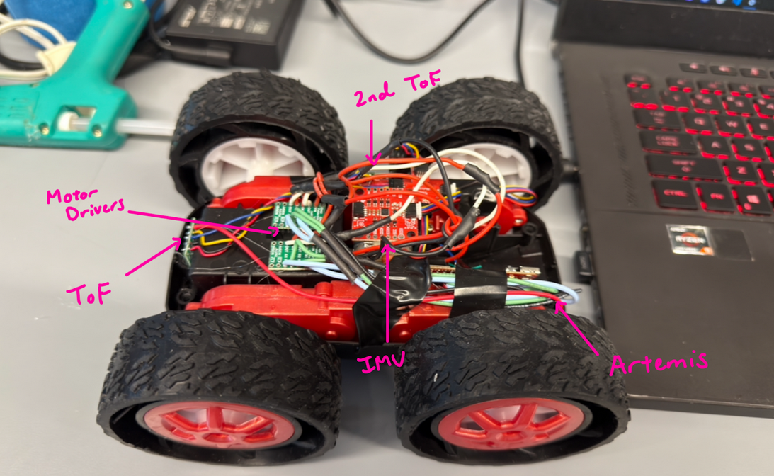
With the A2 pin occupied by one of the ToF’s XSHUT pin, I decided to wire the inputs of the right motor driver to pins A0 and A1, and the inputs of the left motor driver to pins A14 and A15.
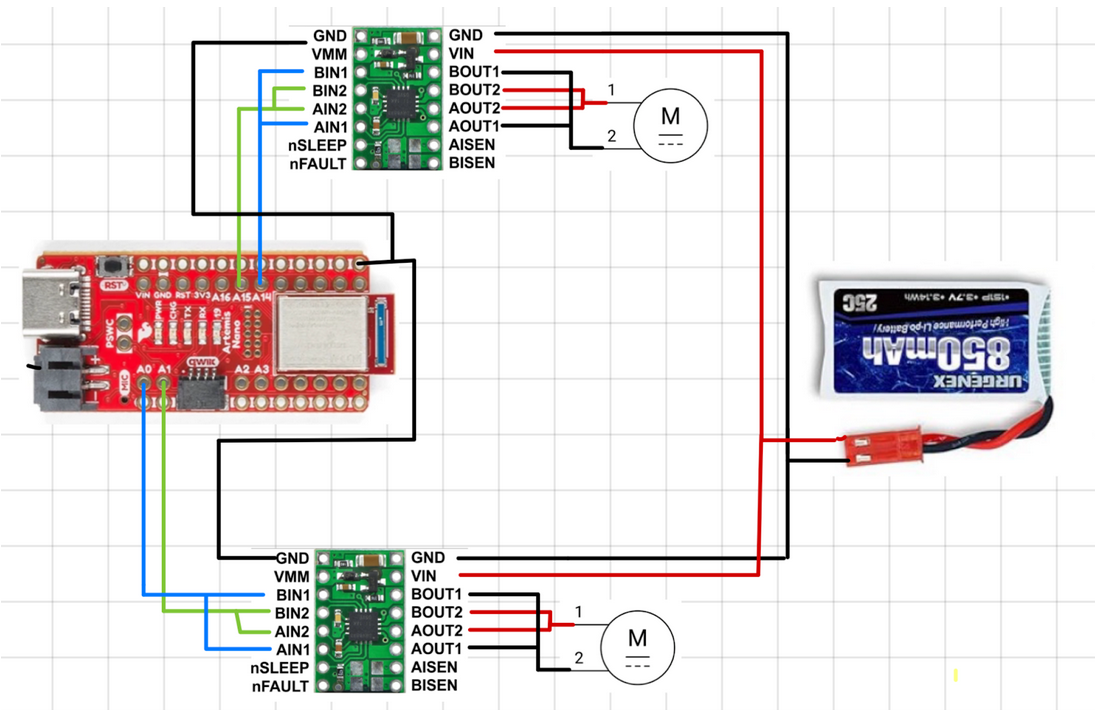
The Artemis and the motor drivers are powered by separate batteries because we don’t want the Artemis board to brownout or lose enough voltage to not send or receive any data from other peripheral components. This would happen anytime the motors draw current if one battery is used.
2. Lab Tasks
1. Connect the necessary power and signal inputs to one dual motor driver
At this point, we want to keep the motor driver powered by an external power sypply. The reasonable settings for the power supply is 3.7 V as it matches the nominal voltage of the battery powering each motor driver.
2. Use analogWrite commands to generate PWM signals
The following code was writtent to generate a PWM signal to power the first motor driver:
The following figure shows the motor driver connected to the oscilloscope and power supply:
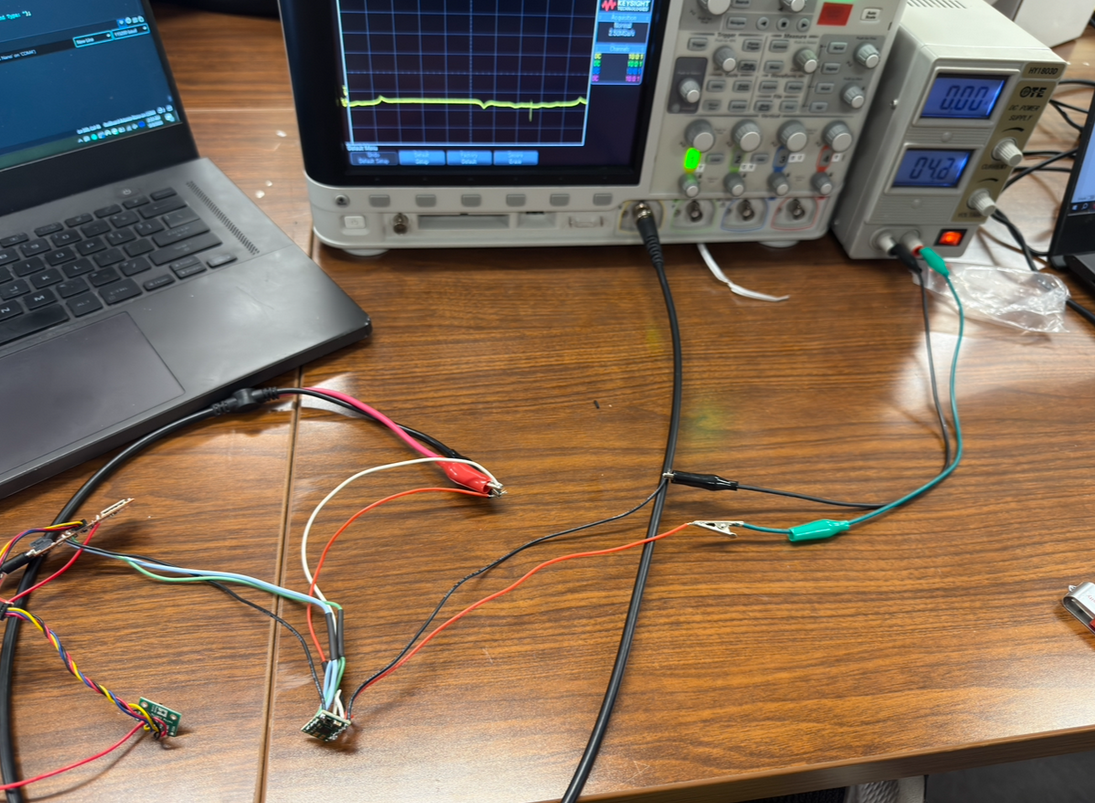
The following video shows the read signal on the oscilloscope after running the GENERATE_PWM command:
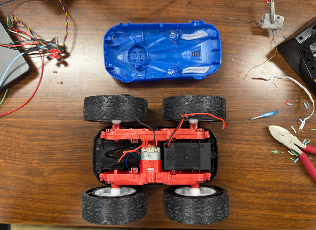
3. Take your car apart!
4. Show that you can run the motor in both directions
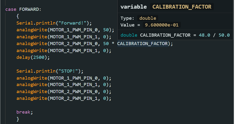
The following code was writtent to run the motor in both directions:
5. Power the motor driver from the 850mAh battery instead of the power supply
6. Repeat the process for the second motor and motor driver
Each previous step was repeated to ensure that the second motor and motor driver was integrated correctly to the rest of the car. An oscllioscope was used to check that clean PWM signals were being sent to the motor driver and that the motor was able to move forward and backwards.
7 & 8. Install everything inside your car chassis, and try running the car on the ground; explore lower limit in PWM
After installing everything into the car, the lower limit for a PWM signal was explored. For my car, the lower limit is 28.
9. Implement a calibration factor
To ensure that the car drives straight, a 48/50 power split was created between the right and left motors.
10. Open-loop control
The following code and video shows open loop, untethered control of my robot.
Additional tasks for 5000-level students
1) From the video attached to task 2, the oscilloscope shows that the frequency that analogWrite generates is about 183.3 Hz. A PWM signal at this speed is considered to be slow as motor drivers can often have input frequencies in the kHz range. The frequency of a PWM signal affects how smoothly the power is delivered to the motor. If the frequency is high, the motor sees a smooth voltage equivalent to the average of the pulses, rather than seeing the individual pulses, due to the motor’s inductance. There are benefits of increasing the frequency, such as reducing audible noise, smoothing out motor torque, and reducing current ripple by keeping the current draw steady.
2) After having the robot roll forward for a period of two seconds at a PWM value of 28, the lowest value that keeps the robot moving is 25.
Collaborators
For Lab 4, I collaborated with Sean Zhen (sz378). I also referenced to Aidan Derocher’s and Angela Voo’s pages.
Back to Labs