Lab 5 - Linear PID
1. Prelab
To set up a robust system for debugging the PID controller, I plan to send gains for my PID controller each time I run a closed-loop command. For this lab, I plan to send information for Kp, Ki, Kd, and the amount of time the robot is commanded before the robot “times out” and stops. This allows the robot to stop after a specified period of time whether or not the robot has Bluetooth connection.
This can be done by using the ble.send_command function in Python, which allows new gains to be updated each time without needing to upload new code. The following Arduino code shows the framework of the command for this lab:
Whenever a closed-loop command is requested, debugging data is stored in arrays and is then sent to a notification handler. The time-stamped debugging data that I chose to collect are sensor data from the ToF sensors and the output from the PID controller.
2. Lab Tasks
1. Position Control
From lab 4, we know that the maximum PWM value for the motors is 255. To determine an appropriate limit for the proportional controller, we can use the maximum expected error. As the ToF sensors are currently operating in short range mode, the maximum range is 1.3 meters, and we expect the robot to stop at a range of 0.304 meters, which gives a max error of 0.996 meters. With this error, the maximum Kp is 255 / 996 mm = 0.256.
The following code shows the implemented PID controller:
A PID controller was used to ensure that as much steady-state error was removed from the final position of the robot and to ensure smooth motion during closed-loop control. The values of the PID controller are Kp = 0.045, Ki = 0.11, Kd = 0.08. A low-pass filter was used on the derivative controller to smooth the input from this branch with a = 0.1. This value was empirically chosen to generate a derivative controller with no rapid velocity changes. Also, derivative kick was eliminated by ignoring the first reading to prevent a large change in error for the derivative branch.
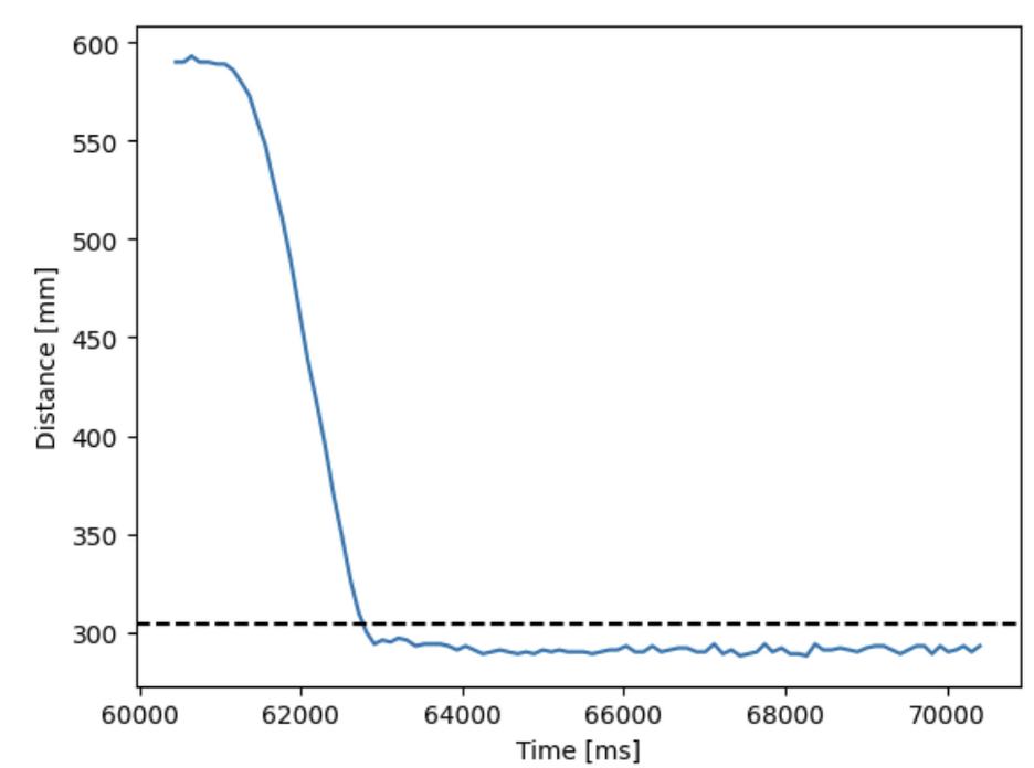
To test the robustness of the controller, the robot was set at three different distances within the range of the ToF sensor. The first test was conducted at 4 feet, and the following tests are conducted at three feet and then two feet.
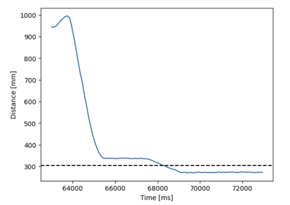
Test #1: 4 feet
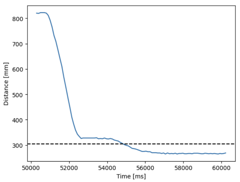
Test #2: 3 feet
Test #3: 2 feet
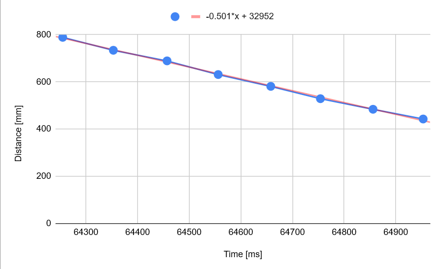
Max achieved speed:
The max achieved speed was during test #1 in which an average of 0.5 m/s.
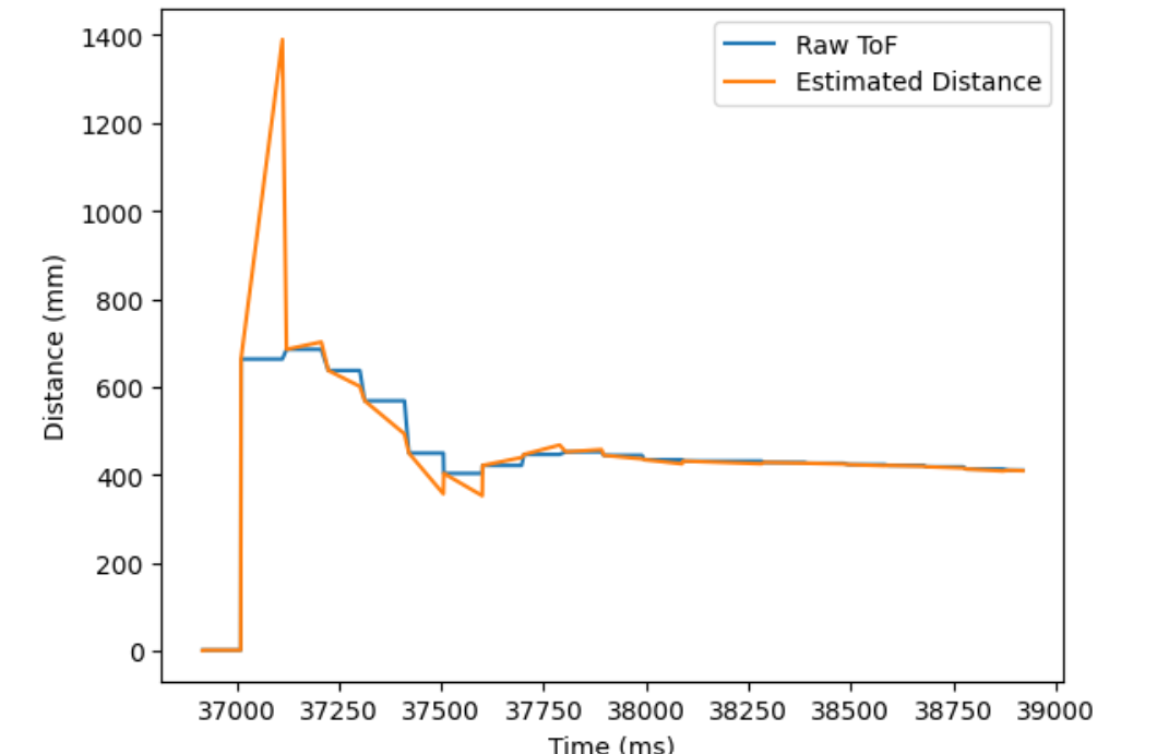
2. Extrapolation
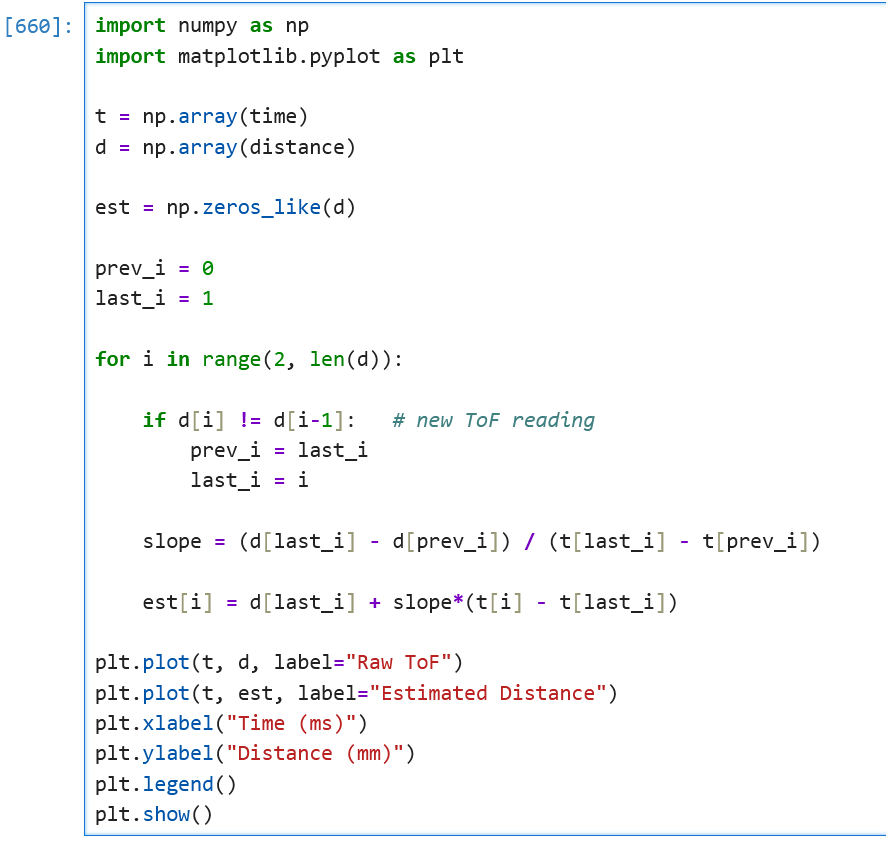
The frequency that the ToF sensor is returning new data is about 10 Hz (~100 ms), which is currently limiting how frequent the PID loop updates. To decouple these two rates, the PID loop should update whether or not there is new data from the ToF sensor. This is done by removing the while (!distanceSensor1.checkForDataReady()) {delay(1); } . In 2839 ms, 1385 updates were given, so this equal to a frequency update of 487 Hz, which is 48 times faster than the previous command.
The following was written in Python to extrapolate new ToF values based on recent sensor values.
Tasks for 5000-level students
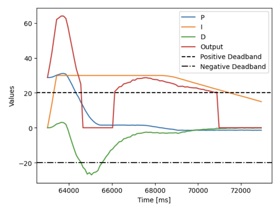
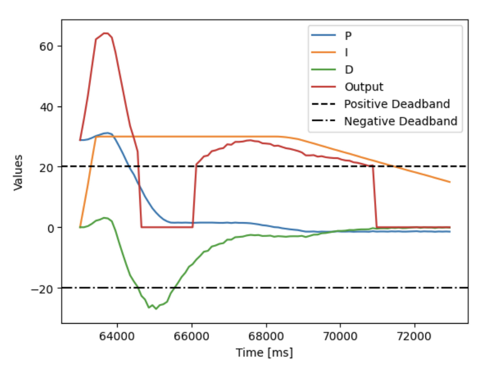
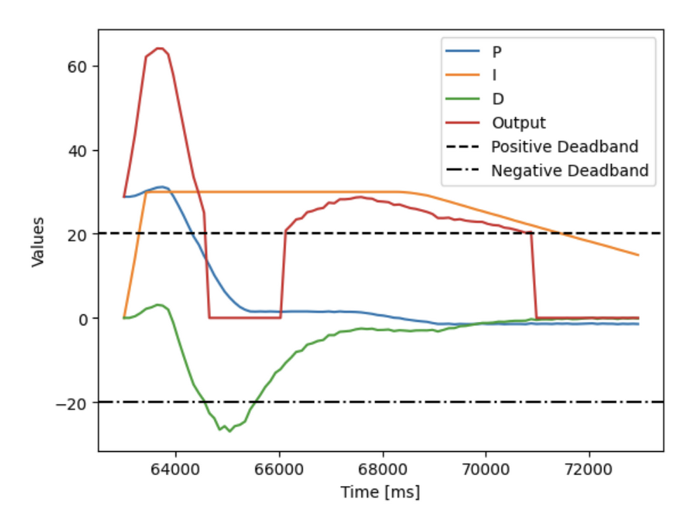
Integrator windup protection is required to prevent PID controllers from accumulating massive, excessive error signals when actuators saturate. This was implemented in my controller by creating a limit on how much the integrator controller can contribute to the overall output of the PID controller.
A clamp value of 30 was chosen, which helped limit the strength of the integrator controller. This can be seen in the highlighted region in the following figure.
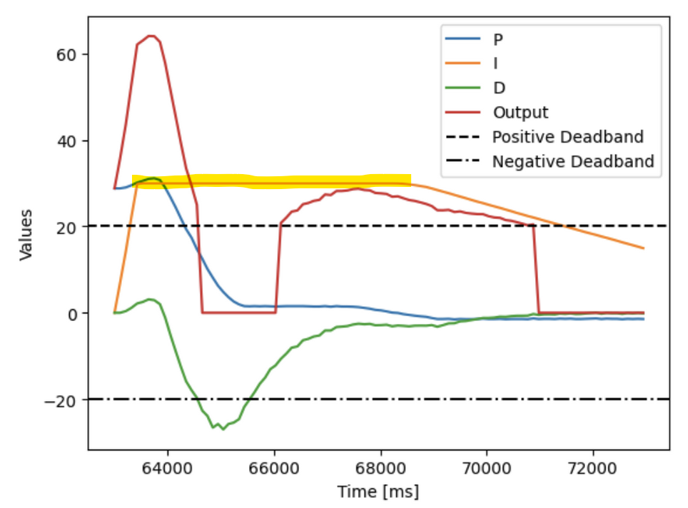
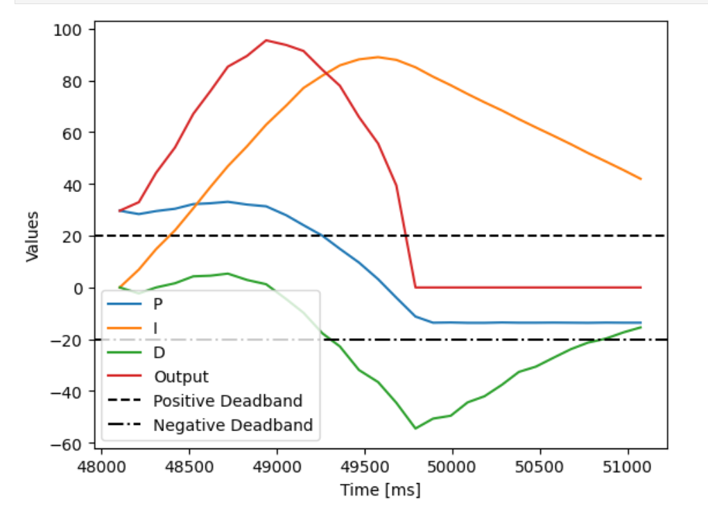
Without windup protection, the integrator controller dominates the PID loop and causes the vehicle to overshoot the setpoint.
Collaborators
For Lab 5, I collaborated with Sean Zhen (sz378).
Back to Labs