Lab 8 - Stunts
For this lab, my robot will be conducting Task B: Drift. To complete a drift, the robot will complete 3 different steps:
- Using open-loop control, drive towards the wall until a target distance is reached.
- Once the target distance is reached, start a differential turn in which the right motor spins forward while the left motor spins backwards for a set power and time.
- After the turn is complete, request each motor to drive forwards away from the wall.
Step 1: Drive forwards
The distance_to_turn is 1300 mm, the output_straight PWM value is 90, and the CALIBRATION_FACTOR is 0.82 to ensure that the robot drives straight.
The turn_flag and turning variables are first initialized as false, which indicates that the robot has not reached the conditions to start the turn. When the distance from the ToF sensor is less than distance_to_turn, turn_flag and turning both change to true. With the turn_flag set to true, the if statement will not run again and ignores any future distance readings that are less than distance_to_turn. This prevents the robot from turning more than once during the stunt.
Step 2: Drift
The output_turn PWM value is set to 120 with the same CALIBRATION_FACTOR, and delay_time is set to 330 ms. delay_time is the variable that controls the amount of time the robot spends drifting using a differential turn.
Once the amount of time since the start of the turn has exceeded delay_time, the turning variable is set to false to exit the turning state.
Step 3: Drive away from wall
Once the turn is completed, the robot returns to the FORWARD STATE, which is the same state as step 1.
Videos
In each video, the robot starts approximately 3 meters from the wall due to space constraints. The neon yellow tape indicates 3 feet from the wall. Due to the friction of the floor, I was unable to have the robot rotate about its center during the drift similar to the example shown in the lab prompt. Instead, each drift consists of the robot visually performing a variable-radius turn with a differential PWM input as the wheels slide at the beginning of the turn and quickly regaining traction to complete the 180-degree turn.
Graphs
The provided graphs shows the distance sensor readings and the motor PWM inputs from one run.
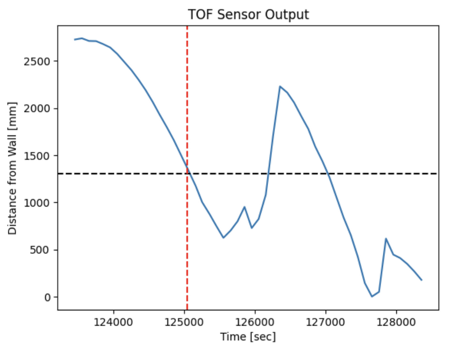
The vertical dashed line indicates the time of 125050 ms in which the distance sensor detected a distance that is less than 1300 mm. This graph also shows the effect of the turn_flag preventing the robot from conducting more than one drift.
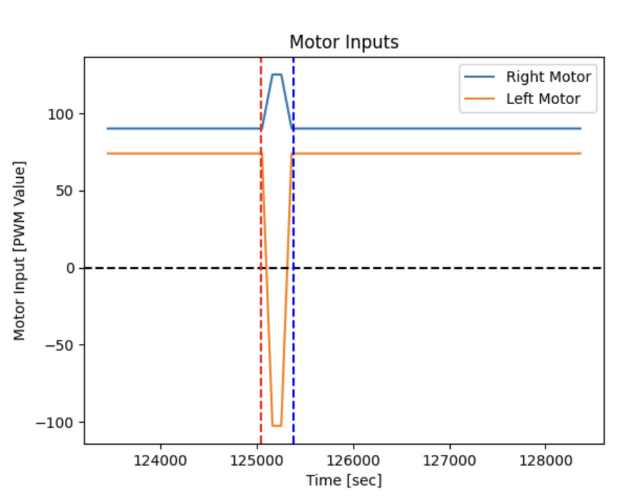
The blue vertical line shows a delay_time of 330 ms after the turn has started. The two different PWM values shown as the robot is driving forwards shows the effect of the CALIBRATION_FACTOR to ensure that the robot drives straight. To make a differential turn, the left motor must rotate backwards while the right motor continues to rotate forwards.
Discussion
By not using a closed-loop PID control and instead using open-loop control, PWM values and delay_time can be easily chosen to allow the robot to complete a drift. Each of the three runs were successful as the robot did not hit the wall and made a 180-degree turn. Only the distance sensor is used to perform this stunt as this allows less variables that need to be tuned. While a IMU can provide more accurate turns by using the gyro data, it was not necessary as the delay_time can be adjusted to complete a 180-degree turn. A Kalman filter would also allow the robot to predict the distance from the wall given few distance readings, but was also not necessary as the robot reacts quickly to not hit the wall by setting a large enough distance_to_turn value.
Collaborators
For Lab 8, I worked with Sean Zhen.
Back to Labs