Lab 12 - Inverted Pendulum
Introduction
For this lab, I was able to have the robot balance on one set of wheels for a short period of time. After conducting many trials, the longest the robot was able to balance for was approximately 7.5 seconds. In each trial, the starting position of the robot was approximately 90 degrees upright from the ground. Both a proportional controller and a PI controller were explored in this lab with the proportional controller providing longer balances while the PI controller provided more stable balances. I also explored using a complementary filter combining the accelerometer data and gyro data, but I eventually settled on using the gyro data. The writeup will go into detail the different options explored and why certain decisions were made.
Implementation
In the early stages of debugging the inverted pendulum, I noticed that the robot needed a much higher PWM value to spin the wheels in one direction compared to the other. While holding the robot in the air, a minimum PWM value of 90 was needed to spin the wheels in the “reverse” direction, while a small PWM value of 1 was significant enough to create a sharp impulse to the wheels in the “forward” direction. After discovering this phenomena, I implemented a “two-way” PID controller in which different gains were used for each direction. To solve the higher PWM value needed to spin the wheels in the reverse direction, a static gain Ks was added whenever the wheels need to spin in this direction.
To balance the robot, I used the gyro data to measure the accumulated difference in pitch from its starting position. The pitch in degrees was used as the “error” for the PID controller. In addition, to prevent the robot from running away once it fails the balance, I wrote a conditional to set the PWM values to 0 once it tips over. The following code snippets shows the implementation of the “two-way” PID controller.
From the conducted trials, the robot was quick enough to react to itself tilting from the upright position. In a 7.5 second period, 220 data points were collected, which means that the PID controller updates at ~30 Hz. This was fast enough for the robot to balance for periods longer than 4 seconds, so, therefore, a Kalman filter was not needed to balance the car and was not implemented for the inverted pendulum.
Tuning of Controller
To obtain the gains for the trials shown below, a low Kp was used for the forward direction, starting at 0.01. Kp_for was increased until the robot was successfully able to tip in the opposite direction. Once Kp_for has been tuned, Kp_rev was tuned in a similar fashion. Because more power was needed to power the wheels in the reverse direction, a higher Kp_rev was used. As mentioned before, the robot needed a high PWM value to cause the wheels to spin in one direction, while a very small PWM value in the forward direction causes the wheels to spin rapidly. Because of this behavior, small precise inputs were hard to implement, so the Kp values were tuned to have the robot oscillate back and forth quickly. To improve the stability, Ki values were later used.
Data and Video of Proportional Controller
The longest balance using a proportional controller was ~7.5 seconds.
The gains were Kp_for = 0.1, Kp_rev = 1.3, and Ks = 90. The following data collected from the gyro and PID controller are shown below.
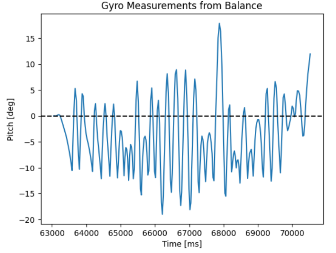
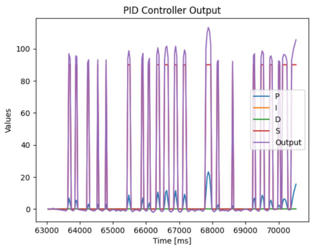
From the above figure, you can see the significant asymmetry in PWM output for each direction and the two-way PID controller in action with the large static gain applied only to the reverse direction.
Data and Video of PI Controller
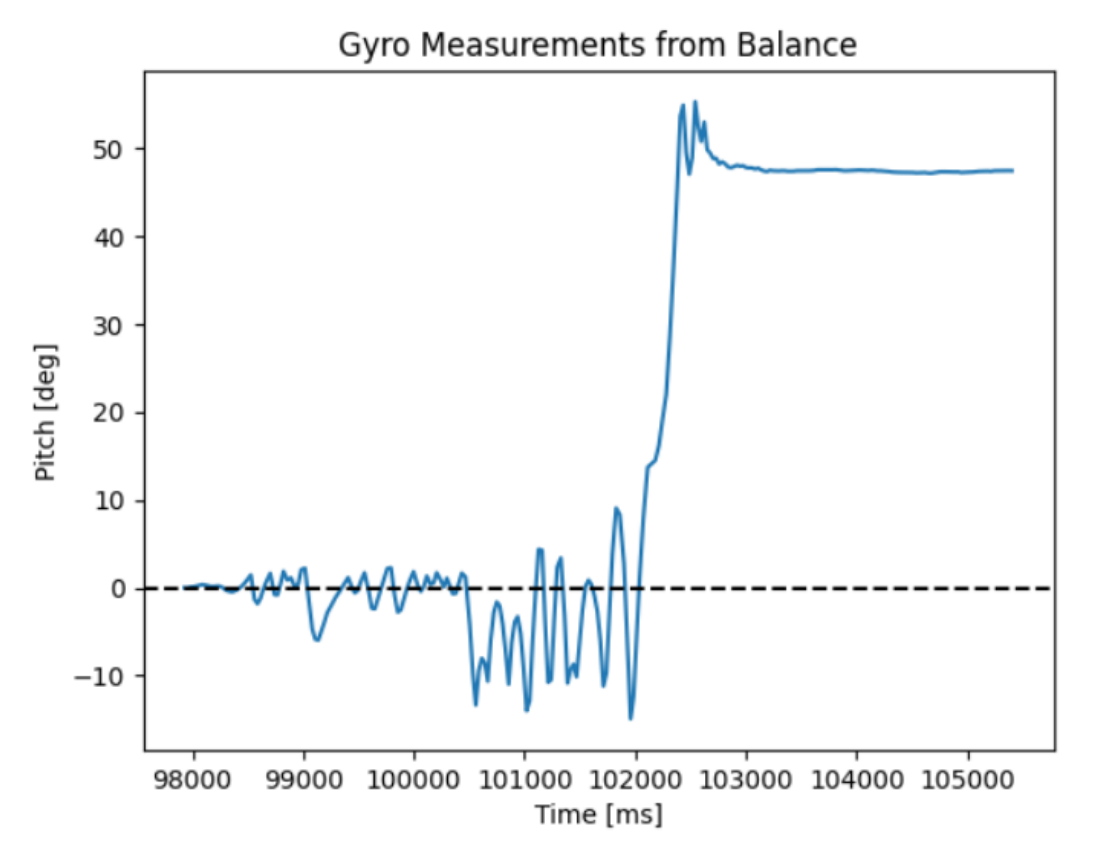
The longest balance using a PI controller was ~4 seconds.
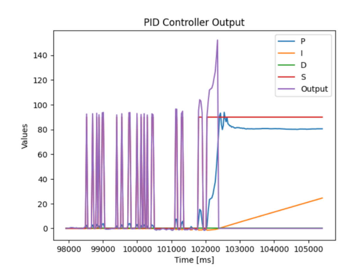
The gains were Kp_for = 0.1, Kp_rev = 1.8, Ki_for = 0.01, Ki_rev = 0.17, and Ks = 90. The following data collected from the gyro and PID controller are shown below.
Discussion on P vs. PI Controller
The longest run was obtained by only using a proportional controller. In an attempt to improve the stability of the inverted pendulum and prevent the robot from driving away from its initial location, I tried to implement a PI controller. However, the integral controller could not react fast enough as the robot frequently tipped back and forth, which caused the accumulated errors to be very small and act in the opposite direction of the intended control which can be seen in the above figure. A high Ki also introduced more oscillations to the system and caused the robot to start driving before I released it, so a low Ki was used for each trial. While the lower Ki values improved the stability of the robot at small angles, it had trouble balancing the car once it tipped further than ~10 degrees.
Why the Complementary Filter was Not Used
From the data collected from the best trial of the PI controller, you can notice that the gyro measures ~50 degrees once the robot tips over. This is due to the drift of the gyro on the IMU and its loss of accuracy when sustained to high accelerations. To improve this, I attempted to use a complementary filter to fuse the accelerometer data and gyro data. However, after attempting to tune the alpha value of the complementary filter, I was unable to produce reliable balances.
The following figure shows the complementary filter with an alpha of 0.90 when holding the robot upright:
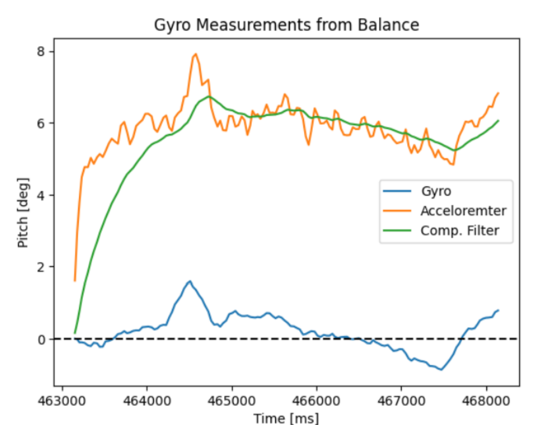
As noted in previous labs and in class, the accelerometer has more noise but not a noticeable drift, while the gyro has less noise. However, at this alpha value, the filter relied more on the accelerometer data. As shown in the figure above, you can see the accelerometer data start out at 6 degrees when holding the robot upright. Having a PID controller that trusted the accelerometer data more is difficult as it heavily relied on the robot being perfectly upright when it first starts. This would cause the robot to start driving before released, which is a significant issue for my robot as any PWM value larger than 1 in the forward direction causes the robot to have an extreme impulse and immediately tip over. Higher values of alpha (which made the gyro data be trusted more) caused the filter to react slower to changes in pitch, which is not optimal for this lab. Therefore, I decided to not use the complementary filter and only rely on gyro data for my balances.
Further Discussion
While not documented, during the ECE showcase day, the robot was able to balance itself after a few seconds and settle in stable equilibrium with no additional motor inputs while using a proportional controller. While this was a cool feat, I did not collect the data and was also not recording at the time of the this trial.
While I wanted to attempt to start the car from the ground position, I was unable to have the car start in the normal position and flip and balance itself upright. This was due to time constraints along with multiple exams and projects during the final weeks. If I had more time, I would have attempted this method. If I were to implement this method, I would have the robot drive forward quickly and brake to cause robot to pop a wheelie. Once the gyro reads a pitch value larger than ~45 degrees, the PID controller will then be engaged.
Collaborators
For Lab 12, I did not work with any other collaborators.
Back to Labs